
Page 279 - The Tribology Handbook
P. 279
824 Mechanical seals
SEAL PERFORMANCE The materials chosen must also have good corrosion
resistance, particularly since one seal face is usually
The main factors which determine the operating limits of carbon-graphite which generates a high electrolytic poten-
mechanical seals are:- tial with most metals, when in an electrolyte.
For the components other than the seal faces, such as
1. The stability (boiling etc.) of the fluid film between the seal chambers, springs and shaft sleeves, the basic ma-
seal faces. terial is austenitic stainless steel (18/8/3) progressing as
2. The wear life of the seal face materials. increasing chemical resistance is required to Hastelloy B
3. The compatibility of the materials, from which the seal (Ni 6VCo 2/Mo 28/Fe 5) and Hastelloy C (Ni 5/co
is made with the sealing environment. 2.5/Cr 15.5/Mo 16/W 4/Fe5). It is an advantage to coat
4. Temperature of operation. the shaft sleeve under the sliding packing with a hard
facing to reduce abrasion and corrosion.
When operating correctly the sealing faces are separated Temperature has a major effect on the choice of
by a very thin fluid film of 0.25-8 pm thick. packing/secondary sealing materials, as shown in Table
Rubbing contact occurs during starting and stopping, 24.4.
and occasionally at normal speeds. The material combina-
tions used, therefore, need to be selected for adequate
friction and wear performance, and Table 24.3 gives some
general guidance. Table 24.4a The effect of temperature on
PV values for mechanical seals are calculated in a secondary sealing materials and design
different way from the more usual load per unit projected
area times rubbing velocity. Below Vertical shafts with double Use synthetic
In a mechanical seal P is taken as the pressure drop -75°C seal arrangement rubber or PTFE
across the seal in bar and V is the mean sliding velocity at (Seals warm gas or vapour packings
the interface in metres per second. instead of cold liquid on
With unbalanced seals 100 to 140% of the sealed horizontal shaft layout)
pressure acts on the seal faces. Balanced seals have part of -75°C Vertical or horizontal shafts Use synthetic
the sealed pressure hydraulically relieved to reduce the 30°C with double seal arrangement rubber or PTFE
force applied to the seal faces. packings
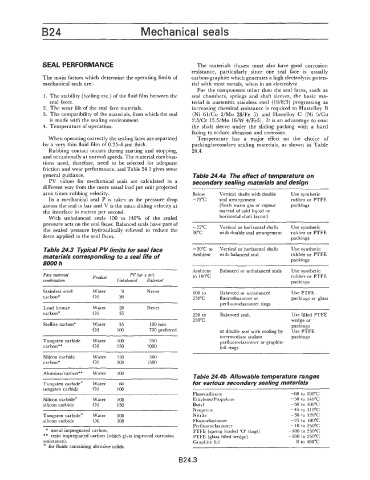
Table 24.3 Typical PV limits for seal face -30°C to Vertical or horizontal shafts Use synthetic
materials corresponding to a seal life of Ambient with balanced seal rubber or PTFE
8000 h packings
Ambient Balanced or unbalanced seals Use synthetic
Face material Product PV bar x m/s to I00"C rubber or PTFE
combination Unbalanced Balanced packings
Stainless steel Water 9 Never 100 to Balanced or unbalanced Use PTFE
carbon* Oil 30 250°C fluoroelostomer or packings or glass
perfluoroelastomer rings
Lead bronze Water 20 Never
carbon* Oil 35 250 to Balanced seal, Use filled PTFE
250°C wedge or
Stellite carbon* Water 35 100 non- packings
Oil 100 700 preferred or double seal with cooling by Use PTFE
~~~ ~ intermediate sealant packings
Tungsten carbide Water 100 250 perfluoroelastomer or graphite
carbon** Oil 150 IO00 foil rings
Silicon carbide Water 150 500
carbon* Oil 200 1500
Alumina/carbon** Water 100 Table 24.46 Allowable temperature ranges
Tungsten carbide' Water 60 for various secondary sealing materials
tungsten carbide Oil 100
Fluorosilicone -60 to 100°C
Silicon carbide' Water 100 Ethylene/Propylene -50 to 140°C
silicon carbide Oil 150 Butyl -50 to 100°C
Neoprene -45 to 110°C
Tungsten carbide' Water 100 Nitrile -30 to 120°C
silicon carbide Oil 300 Fluoroelastorner -25 to 180°C
Perfluoroelastomer - 10 to 250°C
* metal impregnated carbon. PTFE (spring loaded '0' rings) -100 to 250°C
** resin impregnated carbon (which gives improved corrosion PTFE (glass filled wedge) - 100 to 250°C
resistance). Graphite foil 0 to 480°C
for fluids containing abrasive solids.
B24.3