Page 350 - The Tribology Handbook
P. 350

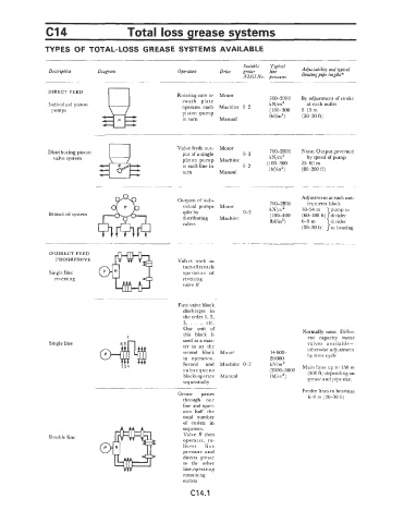
C14                      Total loss grease systems

               TYPES  OF TOTAL-LOSS  GREASE  SYSTEMS  AVAILABLE


                                                                           Suitable   Typical
                Description    Diagram                 Operation    Drive   grease   line    Adjustability and typical
                                                                           ~VLGI~V~. pressures   limiting Pipe lengths*

                DIRECT  FEED
                                                       Rotating cam or  Motor
                                                        swash  plate               700-2000   By adjustment of stroke
                Individual piston                       operates  each  Machine  0-2   kN/m2   at each outlet
                 pumps                                  piston  pump               (100-300   9--15 m
                                                        in turn     Manual         Ibf/in2)   (30-50  ft)


                                                       Valve feeds out-  Motor
                Distributing piston                     put of a single    0-3     700-2000   None. Output governed
                 valve system                           piston  pump  Machine      kN/mZ      by speed of pump
                                                        to each line in    0-2    (100-300   25-60  m
                                                        turn        Manual         Ibf/in2)   (80-200  ft)


                                                       Outputs of indi-                     Adjustment at eachout-
                                                                                              let/meter block
                                                        vidual  pumps  Motor       700-2800   18-54  m   pump to
                                                                                   kN/mZ
                Branched system                         split by           0 -3    (100-400   (60-180 ft)}divider
                                                        distributing   Machine
                                                        valves                     Ibf/in2)   6-9  m   wider
                                                                                             (20-30  ft)  }:o   bearing

                INDIRECT FEED
                  PROGRESSIVE                          Valves  work  in
                                                        turn after each
                Single line                             operation  of
                  reversing                             reversing
                                                        valve R


                                                       First valve block
                                                        discharges  in
                                                        the order  1, 2,
                                                        3,  .  .  .i  etc.
                                                         One  unit  of
                                                        this  block  is                      Normally  none.  Differ-
                                        1                                                     ent  capacity  meter
                Single line                             used as a mas-                        valves  available-
                                                        ter  to  set  the
                                                        second  block   Motor      14 000-    otherwise adjustment
                                                        in  operation.             20 000     by time cycle
                                                        Second   and  Machine  0-2   kN/rn2
                                                        subsequent                 ~2000-3000   Main lines up to  150 m
                                                        blocks operate   Manual    Ibf/in2)   (500 ft) depending on
                                                        sequentially                          grease and pipe size.
                                                                                            Feeder lines to bearings
                                                       Grease   passes
                                                        through  one                          6-9  m (20-30 ft)
                                                        line and oper-
                                                        ates  half  the
                                                        total  number
                                                        of  outlets  in
                                                        sequence.
                Double line                             Valve  R  then
                                                        operates,  re-
                                                        lieves   line
                                                        pressure  and
                                                        directs  grease
                                                        to  the  other
                                                        line, operating
                                                        remaining
                                                        outlets
                                                           C14.1
   345   346   347   348   349   350   351   352   353   354   355