
Page 352 - The Tribology Handbook
P. 352
C14 Total loss grease systems
PIPE- FLOW CALCULATIONS
To attempt these it is necessary that the user should know:
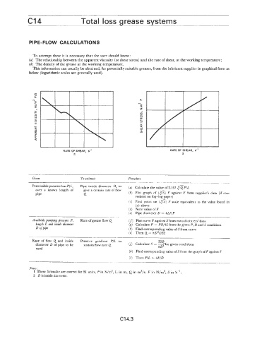
(u) The relationship between the apparent viscosity (or shear stress) and the rate of shear, at the working temperature;
(6) The density of the grease at the working temperature.
This information can usually be obtained, for potentially suitable greases, from the lubricant supplier in graphical form as
below (logarithmic scales are generally used).
.
N . N U
E
E
In
z z
o
Lo
W
E
I- o
E
+ a
z W
W
I
rr v)
a
a
a.
a
RATE OF SHEAR, s-’ RATE OF SHEAR, s-’
S S
Given To estimate Procedure
.... ~ ~~. __
Permissible pressureloss P/L, Pipe inside diameter D, to calculate the value of2,167 fip/~
-
over a known length of give a certain rate of flow
DiDe 0 (b) Plot graph of ($) F against F from supplier’s data (if con-
.I venient on log-log paper)
(c) Find point on (XS) F scale equivalent to the value found in
(a) above
(d) Note value of F
(e) Pipe diameter D = 4LF/P
Available pumping pressure P, Rate of grease flow Q (f) Plot curve F against S from manufacturers’ data
length L and inside diameter (E) Calculate F = PD/4L from the given P, D and L conditions
D of pipe (h) Find corresponding value of S from curve
(i) Then Q = nD3S/32
____ __
Rate of flow Q and inside Pressure gradient P/L to 32Q
diameter D of pipe to be sustain flow rate Q G) Calculate S = - for given conditions
xD3
used
(k) Find corresponding value of S from the graph of F against S
(I) Then P/L = 4F/D
- ~_-___.~-
Notes:
1 These formulae are correct for SI units, P in N/m2, L in m, Q in m3/s. F in N/m2, S in S-’.
2 D is inside diameter.
C14.3