
Page 54 - The Tribology Handbook
P. 54
Steady load pressure fed journal bearings A9
HY DRODY NAMlC BEARINGS
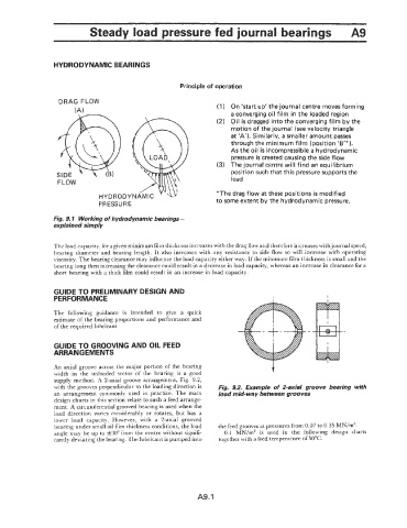
Principle of operation
DRAG FLOW
(A 1 (1) On 'start up' the journal centre moves forming
a converging oil film in the loaded region
(2) Oil is dragged into the converging film by the
motion of the journal (see velocity triangle
at 'A'). Similarly, a smaller amount passes
through the minimum film (position '6'").
As the oil is incompressible a hydrodynamic
pressure is created causing the side flow
(3) The journal centre will find an equilibrium
position such that this pressure supports the
FLOW load
HYDRODYNAMIC ' 'u *The drag flow at these positions is modified
PRESSURE to some extent by the hydrodynamic pressure.
Fig. 9.1 Working of hydrodynamic bearings -
explained simply
The load capacity, for a given minimum film thickness increases with the drag flow and therefore increases with journal speed,
bearing diameter and bearing length. It also increases with any resistance to side flow so will increase with operating
viscosity. The bearing clearance may influence the load capacity either way. If the minimum film thickness is small and the
bearing long then increasing the clearance could result in a decrease in load capacity, whereas an increase in clearance for a
short bearing with a thick film could result in an increase in load capacity.
GUIDE TO PRELIMINARY DESIGN AND
PERFORMANCE I
The following guidance is intended to give a quick
estimate of the bearing proportions and performance and
of the required lubricant.
GUIDE TO GROOVING AND OIL FEED
ARRANGEMENTS
An axial groove across the major portion of the bearing t
width in the unloaded sector of the bearing is a good
supply method. A 2-axial groove arrangement, Fig. 9.2,
with the grooves perpendicular to the loading direction is Fig. 9.2. Example of 2-axial groove bearing with
an arrangement commonly used in practice. The main load mid-way between grooves
design charts in this section relate to such a feed arrange-
ment. A circumferential grooved bearing is used when the
load direction varies considerably or rotates, but has a
lower load capacity. However, with a 2-axial grooved
bearing under small oil film thickness conditions, the load the feed grooves at pressures from 0.07 to 0.35 MN/m'.
angle may be up to +30° from the centre without signifi- 0.1 MN/m2 is used in the following design charts
cantly deviating the bearing. The lubricant is pumped into together with a feed temperature of 50°C.
A9.1