Page 50 - The Tribology Handbook
P. 50

Ring and disc fed journal bearings                                      A8


                                                          JOURNAL  DIAMETER,  in
                                                      5             6             7            8             3
                       4001


                       350C


                       30QC


                       2500

                    C
                    .E
                    >
                    L
                    d
                    W
                    w
                    a
                    u)  2000
                    0
                    z_
                    c
                    E
                    -1
                       1500


                       1000


                        500
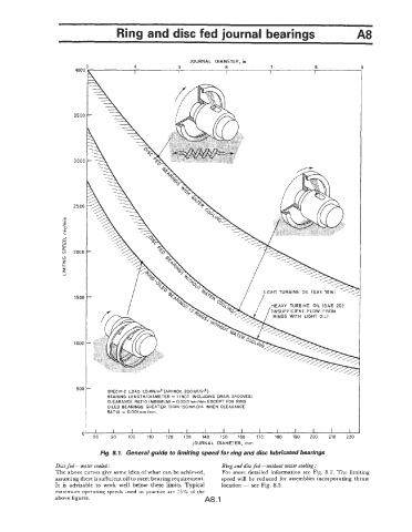
                                 SPECIFIC  LOAD  1.5 MNlmZ (APPROX. 2001bf/in2)
                                 BEARING  LENGTHIOIAMETER = 1 (NOT  INCLUDING  DRAIN GROOVES).
                                 CLEARANCE  RATIO (MINIMUM) = 0.0015mmlmm  EXCEPT  FOR  RING
                                 OILED  BEARINGS  GREATER  THAN  150mm OlA. WHEN  CLEARANCE
                                 RATIO  = 0.001mm/mm.


                          0
                             80   90   100   110   120   130   140   150   160   170   180   190   200   210   220
                                                           JOURNAL  DIAMETER,  mm
                               Fig. 8. I.  General guide to limiting speed for ring and disc lubricated bearings
                  Disc fed-wate?  cooled:                          Ring and disc fed-  without water cooling :
                  The above curves give some idea of what can be  achieved,   For  more detailed information see Fig. 8.2. The limiting
                  assuming there is sufficient  oil to meet bearing requirement.   speed will  be  reduced for  assemblies incorporating thrust
                  It  is  advisable to  work  well  below  these  limits.  Typical   location - see Fig. 8.5.
                  maximum operating speeds used in practice are  75%  of the
                  above figures.                              A8.1
   45   46   47   48   49   50   51   52   53   54   55