
Page 47 - The Tribology Handbook
P. 47
A7 Grease, wick and drip fed journal bearings
Step 6 housing surface area using the power loss found in step 6.
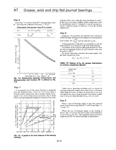
From Fig. 7.5 read the value of F' corresponding to this If this area is too large, a higher oil film temperature must
W'. Calculate the coefficient of fiction p = pCd/d. be assumed and steps 4-7 repeated. It may be necessary to
choose a different grade of lubricant to limit the oil film
Calculate the power loss H in watts temperature.
H= 1.9 x IO-' zp Wdn zp Wdn
Step 8
in lbf m N
Units
rev/rnin revjs Using Fig. 7.4 read off Q' and calculate Q the minimum
oil flow through the film corresponding to the dimensionless
(7
10 -
8- load number, W' x - and the value for hmi&.
6- A large proportion of this flow is recirculated around the
-
~1~74 bearing and in each meniscus at the ends of the bearing.
a- An estimate of the required additional oil feed rate from
-11
LL the feed arrangement is given by a10 and this value may
a" 2- be used in step 9.
E For grease lubrication calculate the grease supply rate
V per hour required Q, from
2 1-
0.8 - Q, = k, x Cd xz x d x b
0
0.6 -
0
[L -
u. 0.4 Table 7.6 Values of kg for grease lubrication
- at various rotational speeds
0.2 -
Journal speed
reolmin
t
I
0.1 I , I , , , , $0 up to 100 0.1
250 0.2
500 0.4
1000 1 .o
Step 7 Under severe operating conditions such as caused by
It is assumed that all the power loss heat is dissipated running at elevated temperatures, where there is vibration,
from the housing surface. From Fig. 7.6 find the value of where loads fluctuate or where the grease has to act as a
housing surface temperature above ambient which corres- seal against the ingress of dirt from the environment, supply
ponds to the oil film temperature assumed in step 4. Read rates of up to ten times the derived Q value are used.
off the corresponding heat dissipation and hence derive the
Step 9
.U 60 Select a type of lubricant supply to give the required
rated lubricant feed using Tables 7.7 and 7.8 and Figs. 7.7,
7.8 and 7.9.
Where the rate of lubricant supply to the bearing is
known, Fig. 7.4 will give the load number corresponding to
a particular hmi& ratio. The suggested design procedure
stages should then be worked through, as appropriate.
0
0 10 20 30 40 50
HOUSING SURFACE TEMPERATURE ABOVE AMBIENT, "C
Fig. 7.6. A guide to the heat balance of the bearing
housing
A7.5