
Page 45 - The Tribology Handbook
P. 45
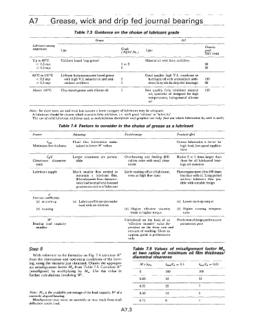
A7         Grease,  wick and drip fed journal bearings


                                     Table 7.3 Guidance on the choice of lubricant grade

                                               Grease                                    Oil
                 Lubricant running                                                                  Viscosi[v
                 temperature                               Grade                                    grade
                              Type                          (NLGI  No.)   7ypes
                                                                                                    IS0 3448
                                       ~
                 Up to 60°C    Calcium based ‘cup grease’              Mineral oil with fatty additives
                   < 0.5  m/s                               1 or2                                   68
                   > 0.5  m/s                              0                                        32
                 60°C to 130°C   Lithium hydroxystearate based grease   Good quality high  V.I.  crankcase  or
                   < 0.5 m/s    with high V.I. mineral oil and anti-   3   hydraulic oil with antioxidant addi-   150
                   > 0.5 m/s    oxidant additives          3             tives (fatty oils for drip-fed bearings)   68

                 Above 130°C   Clay based grease with silicone oil   3   Best  quality  fully  inhibited  mineral   150
                                                                         oil,  synthetic oil  designed  for high
                                                                         temperatures, halogenated  silicone
                                                                         oil

               Notes;  for short term use and total loss systems a lower category of lubricant may be adequate.
                 A lubricant should be chosen which contains fatty additives, i.e.  with good ‘oiliness’ or ‘lubricity’.
                 The use of solid lubricant additives such as molybdenum disulphide and graphite can help  (but not where lubrication by  wick is used).
                             Table 7.4 Factors to consider in the choice of grease as a lubricant

                 Feature            Advantqge                Disadvantage             Practical efect
                        kin         Fluid  film  lubrication  main-                   Grease lubrication  is  better  for
                 Minimum film thickness   tained at lower W’ values                     high load, low-speed applica-
                                                                                        tions

                                    Larger  clearances  are  permis-   Overheating and  feeding  diffi-   Ratios 2 to 3 times larger than
                        Cd/d
                 Clearance  diameter   sible                   culties arise with small clear-   those for oil lubricated bear-
                  ratio                                        ances                    ings are common
                 Lubricant supply   Much  smaller  flow  needed  to   Little cooling effect oflubricant,   Flowrequirement lOto 100 times
                                      maintain  a  lubricant  film.   even at high flow rates   less than with oil. Long period
                                      Rheodynamic flow character-                       without  lubricant  flow  pos-
                                      istics lead tosmall end-loss and                  sible with suitable design
                                      good recirculationof lubricant
                        Ir
                 Friction coefficient
                   (a) at start-up   (a) Lubricant film persist sunder                 (a) Lower start-up torque
                                       load with no rotation
                   (b) running                               (b) Higher  effective  viscosity   (b) Higher  running  tempera-
                                                                leads to higher torque   tures
                        w                                    Calculated  on  the  basis  of  an   Predictionofdesign performance
                 Bearing  load  capacity                       ‘effective viscosity’ value  de-   parameters poor
                  number                                       pendent on  the  shear rate and
                                                               amount of working. Gives an
                                                               approx. guide to performance
                                                               only

               Step 5                                            Table  7.5  Values of  misalignment factor  M,
                 With reference to the formulae on Fig. 7.4 calculate W‘   at two ratios of  minimum oil film thickness/
                                                                 diametral clearance
               from the dimensions and operating conditions cf the bear-
               ing, using the viscosity just obtained. Obtain the appropri-   M x bled   hmi&   = 0.1   h,,/Cd  = 0.01
               ate misalignment factor M, from Table 7.5. Calculate W’
               (misaligned)  by  multiplying  by  M,.  Use  this  value  in   0   100            100
               further calculations involving  W‘.               -____
                                                                    0.05         65              33
                                                                    0.25         25              7
               Notes:  M, is the available percentage of the load capacity W’ of a   0.50   12   3
               correctly aligned bearing.
                 Misalignment may occur on assembly or may result from shaft   0.75   8          1
               deflection under load.
                                                           A7.3