
Page 41 - The Tribology Handbook
P. 41
A6 Porous metal bearings
I N STALLATIO N Table 6.2 Minimum housing chamfers at 45"
General instructions Housing diameter, D Length of chamfer
1 Ensure that the bearings are free of grit, and wash in up to 13 mm (+ in) 0.8 mm (&in)
1.2 mm (&in)
oil if not held in dust-free storage. Re-impregnate if 13 mm to 25 mm (fin to 1 in)
held in stock for more than one year or if stored in 25 mm to 51 mm (1 in to 2 in) 1.6 mm (A in)
2.4 mm (&in)
51 mm to 102 mm (2 in to 4 in)
contact with an oil absorbent material. Over 102 mm (4 in) 3.2 mm (4 in)
2 With a self-aligning assembly (see example in Fig. 6.6):
(a) ensure that the sphere is able to turn freely under T3/(D-T). in2
the action of the misalignment force; 0.2 0.4 0.6 0.8 1.0 1.2 (x10-21
(6) check that the static load capacity of the housing
assembly is adequate; MORE ELASTIC MATERIAL THAN STANDARD
(c) note that the heat dissipation will be less than a POROUS BRONZE AND WITH MORE RIGID HOUSINGS
force-fitted assembly and hence the temperature
rise will be higher.
3 With a force-fitted assembly (see examples in Fig. 6.6): ,
(a) select a mean diametral interference of 0.025+
0.007wD mm (0.001 +O.OOlwD inches) ;
(6) check that the stacking of tolerances of housing
and bearing (see Fig. 6.4) keeps the interference Oe3 - ROUGH SURFACE FINISH,
between about half and twice the mean inter- - INSUFFICIENT TAPER OR
LEAD-IN AT THE MOUTH
ference ; 0.1 -
(c) allow adequate chamfer on the housing (see Table OF THE HOUSING I I l l
6.2 for details); 00 ; 1 ; d, ; iQ,+ b 10 ;I 12 (xl0-21
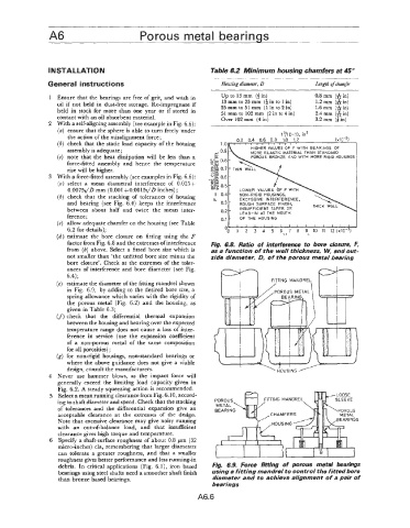
(d) estimate the bore closure on fitting using the F
factor from Fig. 6.8 and the extremes ofinterference Fig. 6.8. Ratio of intepference to bore closure, F,
from (6) above. Select a fitted bore size which is as a function of the wall thickness, w, and Out-
not smaller than 'the unfitted bore size minus the side diameter, 0, of the porous metal bearing
bore closure'. Check at the extremes of the toler-
ances of interference and bore diameter (see Fig.
6.4);
(e) estimate the diameter of the fitting mandrel shown TlNG MANDRE
in Fig. 6.9, by adding to the desired bore size, a
spring allowance which varies with the rigidity of
the porous metal (Fig. 6.2) and the housing, as
given in Table 6.3;
(f) check that the differential thermal expansion
between the housing and bearing over the expected
temperature range does not cause a loss of inter-
ference in service (use the expansion coefficient
of a non-porous metal of the same composition
for all porosities) ;
(g) for non-rigid housings, non-standard bearings or
where the above guidance does not give a viable
design, consult the manufacturers.
4 Never use hammer blows, as the impact force will
generally exceed the limiting load capacity given in
Fig. 6.2. A steady squeezing action is recommended.
5 Select a mean running clearance from Fig. 6.10, accord-
ing to shaft diameter and speed. Check that the stacking
of tolerances and the differential expansion give an
acceptable clearance at the extremes of the design.
Note that excessive clearance may give noisy running
with an out-of-balance load, and that insufficient
clearance gives high torque and temperature.
6 Specify a shaft-surface roughness of about 0.8 pn (32
micro-inches) cla, remembering that larger diameters
can tolerate a greater roughness, and that a smaller
roughness gives better performance and less running-in
debris. In critical applications (Fig. &I), iron based Fig. 6.9. Force fitting Of porous metal bearings
bearings using steel shafts need a smoother shaft finish Using a fitting mandfel to control the fitted bore
than bronze based bearings. diameter and to achieve alignment of a pair of
bearings
A6.6