Page 36 - The Tribology Handbook
P. 36

-
                                             Porous metal bearings                                         A6


                 DESIGN  AND  MATERIAL  SELECTION
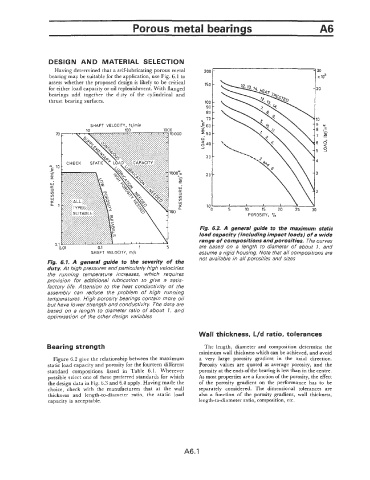
                   Having determined  that a self-lubricating porous metal
                 bearing may be suitable for the application, use Fig. 6.1 to
                 assess whether the proposed design is likely to be critical   150  -
                 for either load capacity or oil replenishment. With flanged
                 bearings  add  together  the  duty  of  the  cylindrical  and
                 thrust bearing surfaces.                            100  -
                                                                     90  -
                                                                       -
                                                                     80
                                                                   N  'O-
                               SHAFT  VELOCITY,  ft/rnin           <60  -
                                                                    2
                                                                     50 -
                                                                    0-
                                                                     40-
                                                                       -
                                                                     30

                                                                       -
                                                                     20


                                                                       2
                                                                                             20
                                                                                                        30
                                                                                                   25
                                                                                        15
                                                                                  10
                                                                     'OO     5
                                                                                   POROSITY,  '10
                                                                   Fig.  6.2. A  general guide  to  the  maximum static
                                                                   load capacity (including impact loads) of a wide
                                                                   range of compositions and porosities.  The curves
                                                                   are  based  on  a  length  to  diameter  of  about  1.  and
                               SHAFT  VELOCITY,  rn/s              assume a rigid housing. Note that all compositions are
                                                                   not available in all porosities and sizes
                       1.  A  general  guide  to  the  severity  of  the
                 duty. At high pressures and particularly  high velocities
                 the  running  temperature  increases,  which  requires
                 provision  for  additional  lubrication  to  give  a  satis-
                 factory  life. Attention  to the heat  conductivity  of the
                 assembly  can  reduce  the  problem  of  high  running
                 temperatures. High porosity bearings contain more oil
                 but have lower strength and conductivity. The data are
                 based  on a length  fo  diameter  ratio  of  about  1.  and
                 optimisation of rhe other design  variables

                                                                   Wall thickness, L/d ratio, tolerances

                 Bearing strength                                    The  length,  diameter  and  composition determine  the
                                                                   minimum wall thickness which can be achieved, and avoid
                   Figure 6.2 give the relationship between the maximum   a  very  large  porosity  gradient  in  the  axial  direction.
                 static load capacity and porosity for the fourteen different   Porosity  values  are quoted  as  average  porosity, and  the
                 standard  compositions  listed  in  Table  6.1.  Wherever   porosity at the ends of the bearing is less than in the centre.
                 possible select one of these preferred standards for which   As most properties are a function of the porosity, the effect
                 the design data in Fig. 6.3 and 6.4 apply. Having made the   of  the  porosity  gradient  on  the  performance  has  to  be
                 choice,  check  with  the  manufacturers  that  at  the  wall   separately  considered.  The  dimensional  tolerances  are
                 thickness  and  length-to-diameter  ratio,  the  static  load   also  a  function  of  the  porosity  gradient,  wall  thickness,
                 capacity is acceptable.                           length-to-diameter ratio, composition, etc.


                                                              A6.1
   31   32   33   34   35   36   37   38   39   40   41