
Page 35 - The Tribology Handbook
P. 35
A5
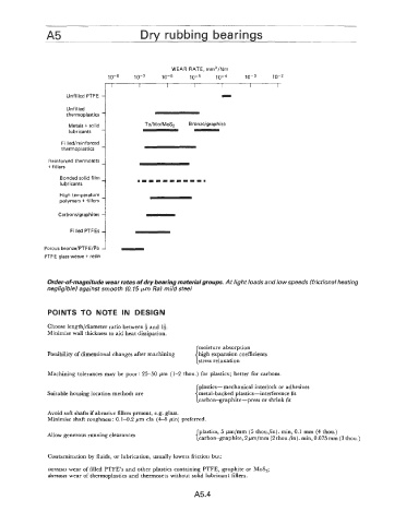
WEAR RATE, mm3/Nm
10-8 10-7 10-6 10-5 10-~ 10-3 10-2
I I I I I i i
Unfilled PTFE I
Unfilled
thermoplastics - -
Metals t solid Ta/Mo/MoS2 Bronze/graphite
lubricants
F illed/reinforced
thermoplastics
Reinforced thermosets
+fillers
Bonded solid film
lubricants
High temperature
polymers + fillers
Carbondgrap hi tes
Filled PTFEs
Porous bronze/PTFE/Pb
PTFE glass weave t resin
Order-ofmagnitude wear rates of dry bearing material groups. At light loads and low speeds (frictional heating
negligible) against smooth (0.15 pm Ra) mild steel
POINTS TO NOTE IN DESIGN
Choose length/diameter ratio between 4 and 14.
Minimise wall thickness to aid heat dissipation.
moisture absorption
Possibility of dimensional changes after machining high expansion coefficients
stress relaxation
Machining tolerances may be poor: 25-50 pm (1-2 thou.) for plastics; better for carbons.
plastics-mechanical interlock or adhesives
Suitable housing location methods are metal-backed plastics-interference fit
carbon-graphite-press or shrink fit
Avoid soft shafts if abrasive fillers present, e.g. glass.
Minimise shaft roughness: 0.1-0.2 pm cla (4-8 pin) preferred.
plastics, 5 pm/mm (5 thou./in). min, 0.1 mm (4 thou.)
Allow generous running clearances
carbon-graphite, 2pm/mm (2 thou./in). min, 0.075 mm (3 thou.)
Contamination by fluids, or lubrication, usually lowers friction but:
increases wear of filled PTFE’s and other plastics containing PTFE, graphite or MoS,;
decreases wear of thermoplastics and thermosets without solid lubricant fillers.
A5.4