Page 37 - The Tribology Handbook
P. 37

A6                          Porous meta I beari ncls

                                                                     i
                                                                             LIMITING
                                                                                       */-I
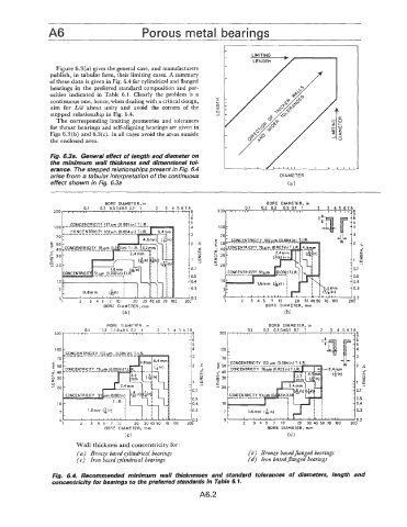
                  Figure 6.3(a)  gives the general case, and manufacturers    LENGTH
                publish, in tabular form, their limiting cases. A summary
                of these data is given in Fig. 6.4 for cylindrical and flanged
                bearings in the preferred standard composition and por-
                osities  indicated  in Table  6.1.  Clearly  the  problem is  a
                continuous one, hence, when dealing with a critical design,   r.-
                                                                  r-
                aim  for  Ud about  unity  and  avoid  the  corners  of  the   $  I
                stepped relationship in Fig. 6.4.
                  The corresponding limiting geometries  and tolerances
                for thrust bearings and self-alipning bearings are given in
                Figs 6.3(b) and 6.3(c). In all cases avoid the areas outside
                the enclosed area.
                                                                     -/
                Fig. 6.3a.  General effect of length and diameter on
                the minimum  wall thickness and  dimensional tol-
                erance. The stepped relationships present in Fig. 6.4      ,   I                I   I   I  ,  ,  ,
                arise from a tabular interpretation of the continuous                 DIAMETER
                effect shown in Fig. 6.3a                                               (a)


                                                                                  BORE  DIAMETER,  in
                                                                           0.1   0.2  0.3   0.5  0.7  1   2  3  4 5 6 7
                                                          :z
                 200   I  I  1  1  .  I                 II 8       2001. I  I  I  ,I I   I   , , , , I  I   I   Ill
                                                          -5
                 100                                      -4
                  70                                      -3                                                3
                'E  50                                    -  2  .E                                          2  .c
                 -  40                                       Er                                               f
                I:
                $  30                                        2
                z                                         I1  F!                                            1;
                w
                J  20                                     -  0.7                                            0.7
                                                          -  0.5                                            0.5
                  10                                      -  0.4                                            0.4
                                                          -                                                 0.3
                   7                                       0.3
                   5                                                                                        0.2
                                                                     1    2   3  4  5  7  10   20  30 4050  70  100   200
                                BORE  DIAMETER,  mm                              BORE  DIAMETER,  mrn
                                      (a)                                              (b)
                                 BORE  DIAMETER,  in                              BORE  DIAMETER,  in
                           0.1   0.2  0.3 0.40.5  0.7   1   2   3  4  5678   0.1   0.2  0.3 0.40.5  0.7   1   2   3  4  5  6 7 8
                                                         '  'Jt    2OOr   I   t   I   II I
                                                          -6
                                                          -5
                                                          -4        100
                                                          -3
                                                                    70
                                                          -2   .5   50
                                                             r    =-  40
                                                             +
                                                             z      30
                                                             a
                                                                  z
                                                                  W
                                                                  2 20
                                                                    10
                            1.6mm  [kir.)      I                                                             0.3
                   7                           I                     7
                                       I       I
                                             ,I,   ,I  _li           5                                       "9
                   51    2   3  4  5  7   10   20  30 40 50  70  100   1   2   3  4  5   7  10   20  30 40 50 70  100   ZOO".&
                                 BORE  DIAMETER,  mm                              BORE  DIAMETER,  rnm
                                       (C)                                              (d i
                        Wall thickness and concentricity for:
                        (a)  Bronze based cylindrical bearings              (b)  Bronze basedflanged bearings
                        (c)  Iron based rylindrical bearings                (d)  hon based flanged bearirigs
                 Fig.  6.4.  Recommended  minimum  wall  thicknesses  and  standard  tolerances  of  diameters,  length  and
                 concentricity for bearings to the preferred standards in Table 6.1.
                                                             A6.2
   32   33   34   35   36   37   38   39   40   41   42