
Page 42 - The Tribology Handbook
P. 42
Porous metal bearings A6
Table 6.3 Spring allowance on force fitting Bore correction
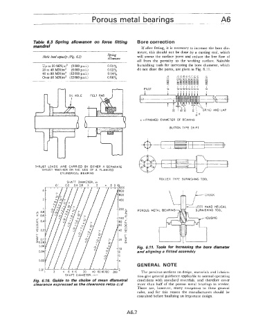
mandrel If after fitting, it is necessary to increase the bore dia-
meter, this should not be done by a cutting tool, which
Static load capan9 fF&. 6.2) Spring will smear the surface pores and reduce the free flow of
allowance
oil from the porosity to the working surface. Suitable
Up to 20 MN/m2 (3 000 psi.) 0.01 yo burnishing tools for increasing the bore diameter, which
20 to 40 hdN/mZ (6 000 psi.) 0.02y0 do not close the pores, are given in Fig. 6.1 1.
40 to 80 MN/mZ (12000 psi.) 0.04%
cccccccc
c
Over 80 NN/mZ (12000 p.s.i.) 0.060/, .- . - ._ .- .- . -. - . - . - ..&
0 -0000000 N 0
0
OF-*----- 00000000
N 0
9 99999999 9
I I I Ill+++ I
PILOT v Ul3l3V~UUW v
IN0 AND LAP
BR
d = FINISHED DIAMETER OF BEARING
BUTTON TYPE DRIFT
THRUST LOADS ARE CARRIED BY EITHER A SEPARATE
THRUST WASHER OR THE USE OF A FLANGED
CYLINDRICAL BEARING
ROLLER TYPE BURNISHING TOOL
SHAFT DIAMETER. in
CHUCK
LEE1 HAND HELICAL
POROUS
Fig. 6.11. Tools for increasing the bore diameter
and aligning a fitted assembly
GENERAL NOTE
u.u I
1 2 4 6 810 20 40 6080100 200 The previous sections on design, materials and lubrica-
SHAFT DIAMETER. mm tion give general guidance applicable to normal operating
Fig. 6.10. Guide to the choice of mean diametral conditions with standard materials, and therefore cover
clearance expressed as the clearance ratio c jd more than half of the porous metal bearings in service.
There are, however, many exceptions to these general
rules, and for this reason the manufacturers should be
consulted before finalising an important design.
A6.7