
Page 44 - The Tribology Handbook
P. 44
rease,
Step 2
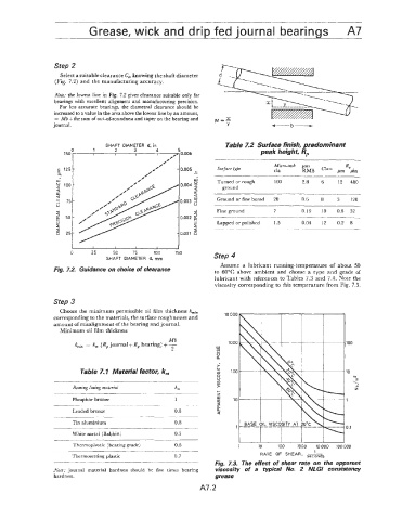
Select a suitable clearance C,, knowing the shaft diameter
(Fig. 7.2) and the manufacturing accuracy.
Note: the lowest line in Fig. 7.2 gives clearance suitable only for
bearings with excellent alignment and manufacturing precision.
For less accurate bearings, the diametral clearance should be
increased to a value in the area above the lowest line by an amount,
= M6+ the sum1 of out-of-roundness and taper on the bearing and
journal. Y -b-
SHAFT DIAMETER d, in Table 7.2 Surface finish, predominant
2 3 4 peak height, Rp
0.005
.-
w 2.8 12 480
0.004 y Turned or rough 100 6
a ground
a
6
0.003 ~~~~ Ground or fine bored 20 0.6 8 3 120
~
a Fine ground 7 0.19 10 0.8 32
0.002 5
w Lapped or polished 1.5 0.04 12 0.2 8
5
0.001 2
0 25 50 75 100 150 Step 4
SHAFT DIAMETER d, mm
Assume a lubricant running-temperature of about 50
Fig. 7.2, Guidance on choice of clearance to 60°C above ambient and choose a type and grade of
lubricant with references to Tables 7.3 and 7.4. Note the
viscosity corresponding to this temperature from Fig. 7.3.
Step 3
Choose the minimum permissible oil film thickness hmi,
corresponding to the materials, the surface roughnesses and 10 000
amount of misalignment of the bearing and journal.
Minimum ail film thickness
Mb
hmin == k, (R, journal-tR, bearing)+- 1000
2 W
IL!
0
a.
i
Table 7.1 Material factor, k, e 100
ffl
0
u
E
Bearing lining materia[ km >
- +-
z
Phosphor bronze 1 W 10
[L
a
~ _ _ a
Leaded bronze 0.8
Q
Tin aluminium 0.8
1
White metal (Babbitt) 0.5
Thermoplastic (bearing grade) 0.6
1
Thermosetting plastic 0.7 RATE OF SHEAR, seconds
~__.__- - Fig. 7.3. The effect of shear rate on the apparent
Note: journal material hardness should be five times bearing viscosity of a typical No. 2 NLGl consistency
hardness. grease
A7.2