Page 52 - The Tribology Handbook
P. 52

Ring and disc fed journal  bearings                                     A8
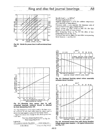


                   1.5                                    2.0
                                                          1.5
                   1.0                                             Specific Load  = I .5 MN/m2
                   0.9
                   0.8                                    1 .o     Bearing length/diameter  = I
                 3 0.7                                    0.9      Ambient  temperature = 2ooC (for ambient  temperature
                  :0.6                                    0.8     4ooC take 80%  of losses shown)
                 20.5                                     0.7      Clearance  ratio  = 0.001 mm/mm  (for clearance  ratio  of
                                                          0.6 P
                 20.4                                             0.0015 mm/mm take 95% of losses shown)
                                                          0.5=    Heavy  turbine  oil  (IS0 VG68  or  SAE  20)  (for  light
                 $0.3                                     0.4
                 g                                                turbine oil take 85% of losses shown)
                 P                                        0.3     Heat  dissipating  factor  as  Fig.  8.9  (for  erect  of  heat
                   0.2
                                                                  dissipating factor see Fig. 8.4)
                                                          0.2     The power loss will be higher for assemblies incorporating
                                                                  thrust location - see Fig. 8.6
                   0.1
                    100    2010  300 400500  8001000   2000  3000
                               JOURNAL  SPEED,  rev/min
                 Fig. 8.3. Guide for power loss in self-contained bear-
                                                                   -
                 ings


                                                                           8  9 10     15  Ibf/in2  20   25  30  35 40


                                                                                              0.15
                                                                                                    0.2
                                                                                                        0.25  0.30
                                                                                      I9 0.1
                                                                   a=       LOCATING  THRUST  SPECIFIC  LOAD,  MN/rnZ
                                                                   4
                                                                     2
                                                                   W
                                                                  Fig.  8.5.  Reduced  limiting  speed  where assembly
                                                                  includes thrust location
                                                                                         Ibf/in2


                 Fig.  8.4.  Showing  how  power  loss  in  self-
                 contained  bearings  (without  thrust)  is  affected
                 by heat dissipating factor KA

                 The heat dissipating casing area A  and/or the heat  trans-
                 fer  coefficient  K  may  both differ from the values used  to
                 derive the load capacity and power loss design charts.
                   Figure 8.4 shows how change in KA  affects power loss.
                 *The ratio
                           New heat dissipating factor KA .
                                                   in Fig. 8.4
                              Heat dissipating factor
                 is given by                                      Fig. 8.6.  Increased power loss with thrust location
                 K for actual air velocity  (Fig. 8.9(b))   actual casing area   {single thrust plain washer - for typical dimensions
                                         -X
                        18 (for still air)   casing area (Fig. 8.9(a))   see Fig, 8.7)
                                                             A8.3
   47   48   49   50   51   52   53   54   55   56   57