
Page 53 - The Tribology Handbook
P. 53
A8 Ring and disc fed journal bearings
in OTHER CLASSIFICATIONS WITH SIMILAR VISCOSITIES
HEAVY TURBINE OIL SAE 20 IS0 VG 68
-
MEDIUM TURBINE OIL IS0 VG 46
LIGHT TURBINE OIL SA€ 1OW IS0 VG 32
100
70
E 60
E 50
40
a
W c $ 30
0
w
z
5 g 20
P .- v) 15
c
z I?
P >
I-
Q
u 0 10
I-
3 298
$ - 7
x 6
'I-T-I -r I I I I I
4' I I I I I I I I
20 30 40 SO 60 70 80 90 100
JOURNAL DIAMETER, rnm OIL TEMPERATURE. 'C
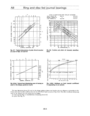
Fig. 8.9. Typicar dimensions of plain thrust annulus Fig 8.8. Turbine and other oil viscosity classifica-
as used in Figs. 8.5 and 8.6 tions
0 ft/min
c"0 1000 2000 3 30
8 50
--.
N
E
4 I
w 5 40
a ' Y
Q - 1600
" 1.0 I-
z - 1400 5 30
v) - u
Q 1200 U
U
V - 1000 fq ;
"I ,' . 800 '- K 20
c
0.5
L
w
- 600
% 10
E 1 , , , , 1 1 , , 1 ] 1 , , 1
- I I I I 5
9 020 100 150 200 250 I-0 1 2 3 4 5 6 7 8 910 1112131415
A .- t
JOURNAL DIAMETER, mm I AIR VELOCITY, m/s
Fig. 8.9(a). Typical heat dissipating area of casing as Fig. 8.9(b). Guidance on heat transfer coefficient
used in the design guidance charts K, depending on air velocity
The heat dissipating factor KA used in the design guidance charts was based on the area diameter relationship in Fig.
8.9(a) and a heat transfer coefficient for still air of 18 W/m2 degC as shown in Fig. 8.9(b). The effect of different dissipating
areas or air velocity over the casing may be judged:
for load capacity Fig. 8.2 (doubled heat dissipating factor KA)
for power loss Fig. 8.4.
A8.4