Page 92 - The Tribology Handbook
P. 92

Profiled pad thrust bearings                                     A16


                                                                  BEARING  TYPE  AND  DESCRIPTION
                                      W
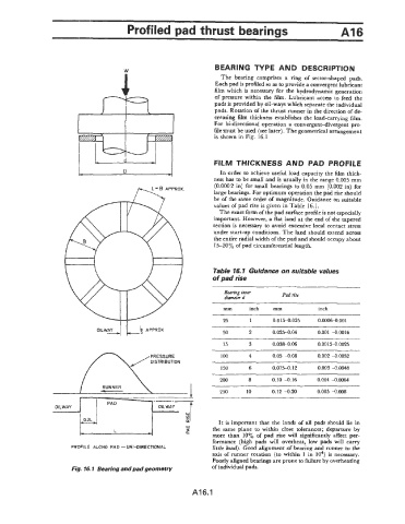
                                                                   The  bearing  comprises a  ring  of  sector-shaped  pads.
                                                                  Each pad is profiled so as to provide a convergent lubricant
                                                                  film which is necessary for  the hydrodynamic generation
                                                                  of  pressure within  the film.  Lubricant  access  to feed  the
                                                                  pads is provided by oil-ways which separate the individual
                                                                  pads. Rotation of the thrust runner in the direction of de-
                                                                  creasing film thickness establishes the load-carrying film.
                                                                  For  bi-directional operation  a convergent-divergent  pro-
                                                                  file-must be used (see later). The geometrical arrangement
                                                                  is shown in Fig.  16.1


                         I  --  I                                 FILM THICKNESS  AND  PAD  PROFILE

                                                                   In order to achieve useful load capacity the film thick-
                                                                  ness has to be small and is usually in the range 0.005 mm
                                                                  (0.0002 in) for small bearings  to 0.05  mm  (0.002 in) for
                                                                 large bearings. For optimum operation the pad rise should
                                                                 be  of the same order of magnitude.  Guidance on suitable
                                                                 values of pad  rise is given in Table 16.1.
                                                                   The exact form of the pad surface profile is not especially
                                                                 important.  However, a flat land at the end of the tapered
                                                                 section is  necessary to avoid  excessive local contact  stress
                                                                 under start-up conditions. The land should extend across
                                                                 the entire radial width of the pad and should occupy about
                                                                  15-20%  of pad circumferential length.


                                                                 Table 16.1 Guidance on suitable values
                                                                 of pad rise
                                                                     Bearing inner    Pad rise
                                                                     diameter d
                                                                     mm     inch    mm           inch
                                                                          ~~
                                                                     25      1     0.015-0.025   0.00064.001
                              O'LWd          APPROX                 50      2      0.025-0.04    0.001 -0.0016
                                                                     75     3      0.038-0.06    0.00I5-0.0025
                                                                   ~   ~~   ~
                                                                    100     4      0.05 -0.08    0.002 -0.0032
                                                                    150     6      0.075-0.12    0.003 -0.0048
                                -                                   200     8      0.10 -0.16    0.004 -0.0064

                                RUNNER
                            I                                       250     10     0.12 -0.20    0.005 4.008
                                                 OILWAY
                                               I
                                                                   It is  important  that  the lands of  ail pads should lie in
                                                                 the  same plane  to  within  close tolerances; departure by
                                                                 more  than  10%  of  pad  rise  will  significantly affect per-
                                                                 formance  (high pads  will  overheat,  low  pads will  carry
                       PROFILE  ALONG  PAD -UNI-DIRECTIONAL       little load). Good alignment of  bearing and runner to the
                                                                 axis of  runner  rotation  (to within  1 in  lo4) is  necessary.
                                                                  Poorly aligned bearings are prone to failure by overheating
                                                                 of individual pads.
                       Fig. 16.1  Bearing and pad geometry


                                                            A16.1
   87   88   89   90   91   92   93   94   95   96   97