
Page 155 - Welding of Aluminium and its Alloys
P. 155
138 The welding of aluminium and its alloys
Table 7.3 Suggested welding parameters – helium shielding, flat position, large
diameter wires
Thickness Root Included Current Voltage No. of Filler Travel
(mm) gap/ angle (A) (V) passes diam. speed
face (degrees) (mm) (mm/min)
(mm)
50 0/5 70/2 550 32 2 each 4.8 250
sided side
75 0/10 30 650 30 3 each 5.6 250
6mm side
root R
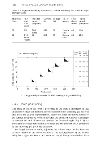
Wire Travel
MIG welded fillet joints Weld dia speed
runs
mm 300–400
mm/min
Fillet weld size – leg length (mm) 12 9 6 2–3 1.6 400–500
1.6
3–4
15
500–600
1.6
1
1
600–700
1.6
0 4 1 1.2 600–700
0 100 150 200 250 300 350
Weld current
7.17 Suggested parameters for fillet welding – argon shielding.
7.4.2 Torch positioning
The angle at which the torch is presented to the joint is important in that
an incorrect angle can result in air entrainment in the shielding gas and will
also affect the degree of penetration. Ideally the torch should be normal to
the surface and pointed forwards towards the direction of travel at an angle
of between 10° and 15° from the vertical, the forehand angle (Fig. 7.18). As
this angle increases penetration decreases and the amount of air entrained
in the shielding gas gradually increases.
Arc length cannot be set by adjusting the voltage since this is a function
of the resistance of the circuit as a whole.The arc length is set by the welder
using both sight and sound, a correct arc length being characterised by a