
Page 188 - Welding of Aluminium and its Alloys
P. 188
Resistance welding processes 171
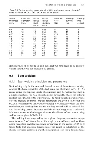
Table 9.1 Typical welding parameters for 50Hz equipment single phase AC
units. Valid for 1XXX, 3XXX, 5XXX and 6XXX alloys
Sheet Electrode Dome Dome Electrode Welding Welding
thickness diameter radius radius force current time
(mm) (mm) (top) (bottom) (kN) (kA) (cycles)
(mm) (mm)
0.4 16 1.0 Flat 1.4 15 4
0.5 16 1.0 Flat 1.5 18 4
0.65 16 2.0 Flat 1.75 21 5
0.8 16 2.0 Flat 2.2 26 6
1.0 16 3.0 Flat 2.7 30 7
1.25 16 3.0 Flat 3.0 33 7
1.6 16 3.0 Flat 3.35 35 8
1.8 16 4.0 4.0 3.6 35 8
2.0 22 4.0 4.0 3.8 41 8
2.3 22 6.0 6.0 4.25 46 10
2.5 22 6.0 6.0 4.7 56 12
3.2 22 6.0 6.0 5.8 76 12
friction between electrode tip and the sheet but care needs to be taken to
ensure that there is not excessive oil present.
9.4 Spot welding
9.4.1 Spot welding principles and parameters
Spot welding is by far the most widely used variant of the resistance welding
process. The basic principles of the technique are illustrated in Fig. 9.1. As
many as five overlapping sheets of aluminium may be welded together in
a single operation.The weld nugget extends through the sheets but without
melting the surfaces of the outer plates. The main welding parameters are
current, pressure and time – typical parameters are given in Tables 9.1 and
9.2. It is recommended that when developing a welding procedure the elec-
trode sizes, the welding time and the welding force should be selected first
and the welding current increased until the desired nugget size is achieved.
Minimum recommended nugget sizes for the thinner of two sheets being
welded are as given in Table 9.3.
The welding force required by three phase frequency converter equip-
ment is some 2 to 5 times that of the single phase AC units and for three
phase secondary rectified machines somewhere in the region of 0.5 to 2
times. Note that excessive forging force will result in indentation of the
sheets, increased distortion and sheet separation. Too low a forging force