
Page 189 - Welding of Aluminium and its Alloys
P. 189
172 The welding of aluminium and its alloys
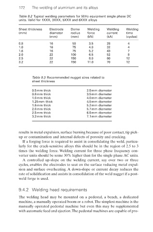
Table 9.2 Typical welding parameters for 50Hz equipment single phase DC
units. Valid for 1XXX, 3XXX, 5XXX and 6XXX alloys
Sheet thickness Electrode Dome Welding Welding Welding
(mm) diameter radius force current time
(mm) (mm) (kN) (kA) (cycles)
0.8 16 50 3.5 28 4
1.0 16 75 4.0 32 4
1.6 16 75 5.2 43 7
2.0 22 100 6.5 52 8
2.5 22 150 8.0 60 12
3.2 22 150 11.0 70 12
Table 9.3 Recommended nugget sizes related to
sheet thickness
0.5mm thick 2.5mm diameter
0.8mm thick 3.5mm diameter
1.0mm thick 4.0mm diameter
1.25mm thick 4.5mm diameter
1.6mm thick 5.2mm diameter
2.0mm thick 5.7mm diameter
2.5mm thick 6.5mm diameter
3.2mm thick 7.1mm diameter
results in metal expulsion, surface burning because of poor contact, tip pick-
up or contamination and internal defects of porosity and cracking.
If a forging force is required to assist in consolidating the weld, particu-
larly for the crack-sensitive alloys this should be in the region of 2.5 to 3
times the welding force. Welding current for three phase frequency con-
verter units should be some 30% higher than for the single phase AC units.
A controlled up-slope on the welding current, say over two or three
cycles, enables the electrodes to seat on the surface reducing metal expul-
sion and surface overheating. A down-slope or current decay reduces the
rate of solidification and assists in consolidation of the weld nugget if a post-
weld forge is used.
9.4.2 Welding head requirements
The welding head may be mounted on a pedestal, a bench, a dedicated
machine, a manually operated boom or a robot.The simplest machine is the
manually operated pedestal machine but even this may be supplemented
with automatic feed and ejection.The pedestal machines are capable of pro-