
Page 193 - Welding of Aluminium and its Alloys
P. 193
176 The welding of aluminium and its alloys
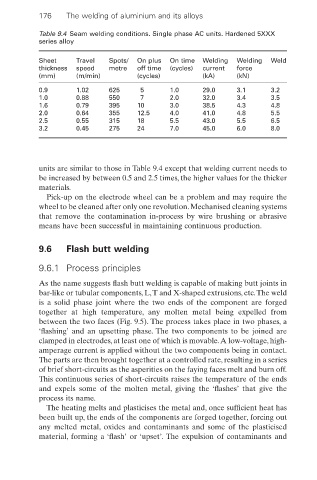
Table 9.4 Seam welding conditions. Single phase AC units. Hardened 5XXX
series alloy
Sheet Travel Spots/ On plus On time Welding Welding Weld
thickness speed metre off time (cycles) current force
(mm) (m/min) (cycles) (kA) (kN)
0.9 1.02 625 5 1.0 29.0 3.1 3.2
1.0 0.88 550 7 2.0 32.0 3.4 3.5
1.6 0.79 395 10 3.0 38.5 4.3 4.8
2.0 0.64 355 12.5 4.0 41.0 4.8 5.5
2.5 0.55 315 18 5.5 43.0 5.5 6.5
3.2 0.45 275 24 7.0 45.0 6.0 8.0
units are similar to those in Table 9.4 except that welding current needs to
be increased by between 0.5 and 2.5 times, the higher values for the thicker
materials.
Pick-up on the electrode wheel can be a problem and may require the
wheel to be cleaned after only one revolution. Mechanised cleaning systems
that remove the contamination in-process by wire brushing or abrasive
means have been successful in maintaining continuous production.
9.6 Flash butt welding
9.6.1 Process principles
As the name suggests flash butt welding is capable of making butt joints in
bar-like or tubular components, L,T and X-shaped extrusions, etc.The weld
is a solid phase joint where the two ends of the component are forged
together at high temperature, any molten metal being expelled from
between the two faces (Fig. 9.5). The process takes place in two phases, a
‘flashing’ and an upsetting phase. The two components to be joined are
clamped in electrodes, at least one of which is movable.A low-voltage, high-
amperage current is applied without the two components being in contact.
The parts are then brought together at a controlled rate, resulting in a series
of brief short-circuits as the asperities on the faying faces melt and burn off.
This continuous series of short-circuits raises the temperature of the ends
and expels some of the molten metal, giving the ‘flashes’ that give the
process its name.
The heating melts and plasticises the metal and, once sufficient heat has
been built up, the ends of the components are forged together, forcing out
any melted metal, oxides and contaminants and some of the plasticised
material, forming a ‘flash’ or ‘upset’. The expulsion of contaminants and