
Page 195 - Welding of Aluminium and its Alloys
P. 195
178 The welding of aluminium and its alloys
Flashing Upset
Upset length
Flashing length
Movement
Force Upset force
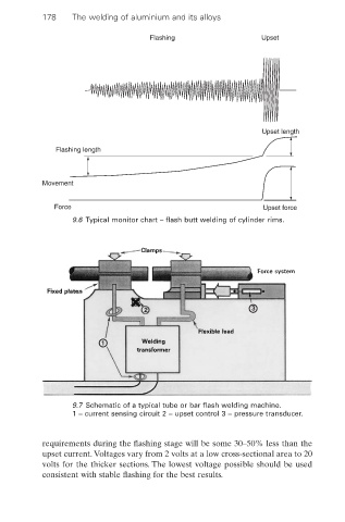
9.6 Typical monitor chart – flash butt welding of cylinder rims.
2 3
1
9.7 Schematic of a typical tube or bar flash welding machine.
1 = current sensing circuit 2 = upset control 3 = pressure transducer.
requirements during the flashing stage will be some 30–50% less than the
upset current. Voltages vary from 2 volts at a low cross-sectional area to 20
volts for the thicker sections. The lowest voltage possible should be used
consistent with stable flashing for the best results.