
Page 102 - The Mechatronics Handbook
P. 102
0066_Frame_C07 Page 12 Wednesday, January 9, 2002 3:39 PM
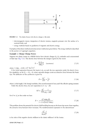
FIGURE 7.11 Two elastic beams with electric charges at the ends.
• electromagnetic tensor, integration of electric tension, magnetic pressure over the surface of a
material body; and
• energy methods based on gradients of magnetic and electric energy.
Examples of the direct method and stress tensor method are given below. The energy method is described
in the section on Lagrange’s equations.
Example 1. Charge–Charge Forces
Suppose two elastic beams in a MEMS device have electric charges Q 1 , Q 2 coulombs each concentrated
at their tips (Fig. 7.11). The electric force between the charges is given by the vector
F = Q 1 Q 2 r (newtons) (7.25)
-----------------
4pe 0 r 3
2
9
= 8.99 × 10 Nm /C 2 .
where 1/4pe 0
If the initial separation between the beams is d 0 , we seek the new separation under the electric force.
For simplicity, we let Q 1 = −Q 2 = Q, where opposite charges create an attractive force between the beam
tips. The deflection of the cantilevers is given by
d = FL 3 1 (7.26)
--------- =
--F
3YI k
where L is the length, Y the Young’s modulus, I the second moment of area, and k the effective spring constant.
Under the electric force, the new separation is d = d 0 − 2δ,
2
1
Q
kδ = ----------------------------------- (7.27)
4pe 0 d 0 –( 2d) 2
For δ << d 0 to first order we have
2
2
Q /4pe 0 d 0 k
d = ------------------------------------------------- (7.28)
2
3
(
1 ( 1/d 0 ) Q /kπε 0 )
–
This problem shows the potential for electric field buckling because as the beam tips move closer together,
the attractive force between them increases. The nondimensional expression in the denominator
Q 2 1
--------------- (7.29)
3 k
pe 0 d 0
is the ratio of the negative electric stiffness to the elastic stiffness k of the beams.
©2002 CRC Press LLC