
Page 100 - The Mechatronics Handbook
P. 100
0066_Frame_C07 Page 10 Wednesday, January 9, 2002 3:39 PM
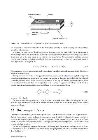
FIGURE 7.9 Elastic beam with two piezoelectric layers (Lee and Moon, 1989).
can be cemented on one or both sides of the beam either partially or totally covering the surface of the
non-piezo substructure.
In general the local electric dipole polarization depends on the six independent strain components
produced by normal and shear stresses. However, we will assume that the transverse voltage or polariza-
tion is coupled to the axial strain in the plate-shaped piezo layers. The constitutive relations between
axial stress and strain, T, S, electric field and electric displacement, E 3 , D 3 (not to be confused with the
bending stiffness D), are given by
T 1 = c 11 S 1 – e 31 E 3 , D 3 = e 31 S 1 + e 3 E 3 (7.20)
The constants c 11 , e 31 , ε 3 , are the elastic stiffness modulus, piezoelectric coupling constant, and the electric
permittivity, respectively.
If the piezo layers are polled in the opposite directions, as shown in the Fig. 7.9, an applied voltage will
produce a strain extention in one layer and a strain contraction in the other layer, which has the effect of
an applied moment on the beam. The electrodes applied to the top and bottom layers of the piezo layers
can also be shaped so that there can be a gradient in the average voltage across the beam width. For this
case the equation of motion of the composite beam can be written in the form
2
2
4
∂ w
∂ w
D--------- + rA--------- = – 2e 31 z o ∂ V 3 (7.21)
-----------
∂x 4 ∂t 2 ∂x 2
where z o = (h S + h P )/2.
The z term is the average of piezo plate and substructure thicknesses. When the voltage is uniform,
then the right-hand term results in an applied moment at the end of the beam proportional to the
transverse voltage.
7.7 Electromagnetic Forces
One of the keys to modeling mechatronic systems is the identification of the electric and magnetic forces.
Electric forces act on charges and electric polarization (electric dipoles). Magnetic forces act on electric
currents and magnetic polarization. Electric charge and current can experience a force in a uniform
electric or magnetic field; however, electric and magnetic dipoles will only produce a force in an electric
or magnetic field gradient.
Electric and magnetic forces can also be calculated using both direct vector methods as well as from
energy principles. One of the more popular methods is Lagrange’s equation for electromechanical systems
described below.
©2002 CRC Press LLC