
Page 99 - The Mechatronics Handbook
P. 99
0066_Frame_C07 Page 9 Wednesday, January 9, 2002 3:39 PM
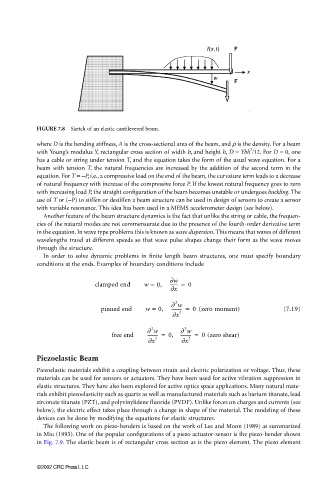
FIGURE 7.8 Sketch of an elastic cantilevered beam.
where D is the bending stiffness, A is the cross-sectional area of the beam, and ρ is the density. For a beam
3
with Young’s modulus Y, rectangular cross section of width b, and height h, D = Ybh /12. For D = 0, one
has a cable or string under tension T, and the equation takes the form of the usual wave equation. For a
beam with tension T, the natural frequencies are increased by the addition of the second term in the
equation. For T = −P, i.e., a compressive load on the end of the beam, the curvature term leads to a decrease
of natural frequency with increase of the compressive force P. If the lowest natural frequency goes to zero
with increasing load P, the straight configuration of the beam becomes unstable or undergoes buckling. The
use of T or (−P) to stiffen or destiffen a beam structure can be used in design of sensors to create a sensor
with variable resonance. This idea has been used in a MEMS accelerometer design (see below).
Another feature of the beam structure dynamics is the fact that unlike the string or cable, the frequen-
cies of the natural modes are not commensurate due to the presence of the fourth-order derivative term
in the equation. In wave type problems this is known as wave dispersion. This means that waves of different
wavelengths travel at different speeds so that wave pulse shapes change their form as the wave moves
through the structure.
In order to solve dynamic problems in finite length beam structures, one must specify boundary
conditions at the ends. Examples of boundary conditions include
∂w
clamped end w = 0, ------- = 0
∂x
2
∂ w
pinned end w = 0, --------- = 0 (zero moment) (7.19)
2
∂x
2
3
∂ w ∂ w
free end --------- = , 0 --------- = 0 (zero shear)
∂x 2 ∂x 3
Piezoelastic Beam
Piezoelastic materials exhibit a coupling between strain and electric polarization or voltage. Thus, these
materials can be used for sensors or actuators. They have been used for active vibration suppression in
elastic structures. They have also been explored for active optics space applications. Many natural mate-
rials exhibit piezoelasticity such as quartz as well as manufactured materials such as barium titanate, lead
zirconate titanate (PZT), and polyvinylidene fluoride (PVDF). Unlike forces on charges and currents (see
below), the electric effect takes place through a change in shape of the material. The modeling of these
devices can be done by modifying the equations for elastic structures.
The following work on piezo-benders is based on the work of Lee and Moon (1989) as summarized
in Miu (1993). One of the popular configurations of a piezo actuator-sensor is the piezo-bender shown
in Fig. 7.9. The elastic beam is of rectangular cross section as is the piezo element. The piezo element
©2002 CRC Press LLC