Page 1092 - The Mechatronics Handbook
P. 1092

TTL Levels                 CMOS Levels
                                                          5 V                   V CC  = 4.5-5.5V
                                                  V CC  = 5V         LOW VOLTAGE
                                                                       LEVELS
                                                                          V  V   = -0.1V
                                                                     3.3 V  OH CC
                                                     HIGH
                                                            V CC  = 2.7-3.6V             V  = 3.85V
                                                                                          IH
                                                                               2.5V
                                                 V OH  = 2.4V  V OH  = 2.4V  V CC  = 2.3-2.7V  V  = 2.5V
                                                                                          TH
                                                 V  = 2.0V  V  = 2.0V  V OH  = 2.0V
                                                  IH
                                                             IH
                                                                        V  = 1.7V
                                                 V  = 1.5V  V  = 1.5V    IH              V  = 1.35V
                                                  TH
                                                             TH
                                                                                          IL
                                                                       V  = 1.2V
                                                                        TH
                                                 V  = 0.8V  V  = 0.8V
                                                  IL
                                                             IL
                                                                         IL
                                                 V OL  = 0.5V  V OL  = 0.2V  V V  = 0.7V  V OL  = 0.1V
                                                                           = 0.2V
                                                                         OL
                                                              Logic Level Specifications
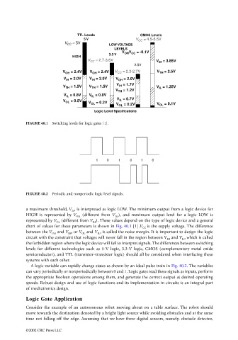
                                 FIGURE 40.1  Switching levels for logic gates [1].

                                                               1    0    1   0    1    0


                                 FIGURE 40.2  Periodic and nonperiodic logic level signals.


                                 a maximum threshold, V IL , is interpreted as logic LOW. The minimum output from a logic device for
                                 HIGH is represented by  V OH  (different from  V IH ), and maximum output level for a logic LOW is
                                 represented by V OL  (different from V IH ). These values depend on the type of logic device and a general
                                 chart of values for these parameters is shown in Fig. 40.1 [1].V CC  is the supply voltage. The difference
                                 between the V OH  and V IH , or V OL  and V IL , is called the noise margin. It is important to design the logic
                                 circuit with the constraint that voltages will never fall in the region between V IH  and V IL , which is called
                                 the forbidden region where the logic device will fail to interpret signals. The differences between switching
                                 levels for different technologies such as 5-V logic, 3.3-V logic, CMOS (complementary metal oxide
                                 semiconductor), and TTL (transistor–transistor logic) should all be considered when interfacing these
                                 systems with each other.
                                   A logic variable can rapidly change states as shown by an ideal pulse train in Fig. 40.2. The variables
                                 can vary periodically or nonperiodically between 0 and 1. Logic gates read these signals as inputs, perform
                                 the appropriate Boolean operations among them, and generate the correct output at desired operating
                                 speeds. Robust design and use of logic functions and its implementation in circuits is an integral part
                                 of mechatronics design.
                                 Logic Gate Application

                                 Consider the example of an autonomous robot moving about on a table surface. The robot should
                                 move towards the destination denoted by a bright light source while avoiding obstacles and at the same
                                 time not falling off the edge. Assuming that we have three digital sensors, namely, obstacle detector,

                                 ©2002 CRC Press LLC
   1087   1088   1089   1090   1091   1092   1093   1094   1095   1096   1097