
Page 1093 - The Mechatronics Handbook
P. 1093
5 V Motor +
Photo Resistor M
Obstacle
Not Present
Not At Edge Transistor
AND
Beacon Visible Switch
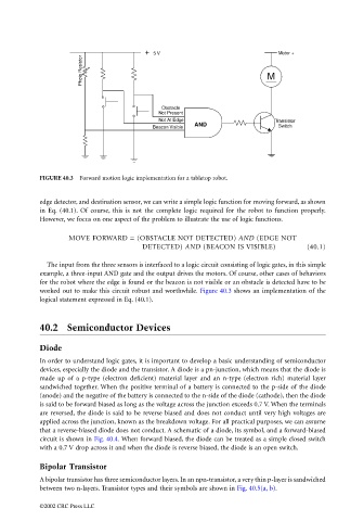
FIGURE 40.3 Forward motion logic implementation for a tabletop robot.
edge detector, and destination sensor, we can write a simple logic function for moving forward, as shown
in Eq. (40.1). Of course, this is not the complete logic required for the robot to function properly.
However, we focus on one aspect of the problem to illustrate the use of logic functions.
MOVE FORWARD = (OBSTACLE NOT DETECTED) AND (EDGE NOT
DETECTED) AND (BEACON IS VISIBLE) (40.1)
The input from the three sensors is interfaced to a logic circuit consisting of logic gates, in this simple
example, a three-input AND gate and the output drives the motors. Of course, other cases of behaviors
for the robot where the edge is found or the beacon is not visible or an obstacle is detected have to be
worked out to make this circuit robust and worthwhile. Figure 40.3 shows an implementation of the
logical statement expressed in Eq. (40.1).
40.2 Semiconductor Devices
Diode
In order to understand logic gates, it is important to develop a basic understanding of semiconductor
devices, especially the diode and the transistor. A diode is a pn-junction, which means that the diode is
made up of a p-type (electron deficient) material layer and an n-type (electron rich) material layer
sandwiched together. When the positive terminal of a battery is connected to the p-side of the diode
(anode) and the negative of the battery is connected to the n-side of the diode (cathode), then the diode
is said to be forward biased as long as the voltage across the junction exceeds 0.7 V. When the terminals
are reversed, the diode is said to be reverse biased and does not conduct until very high voltages are
applied across the junction, known as the breakdown voltage. For all practical purposes, we can assume
that a reverse-biased diode does not conduct. A schematic of a diode, its symbol, and a forward-biased
circuit is shown in Fig. 40.4. When forward biased, the diode can be treated as a simple closed switch
with a 0.7 V drop across it and when the diode is reverse biased, the diode is an open switch.
Bipolar Transistor
A bipolar transistor has three semiconductor layers. In an npn-transistor, a very thin p-layer is sandwiched
between two n-layers. Transistor types and their symbols are shown in Fig. 40.5(a, b).
©2002 CRC Press LLC