Page 1098 - The Mechatronics Handbook
P. 1098

0066_Frame_C40  Page 8  Wednesday, January 9, 2002  8:21 PM


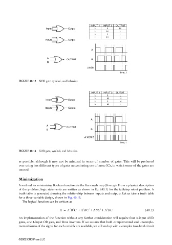
                                                                 INPUT 1  INPUT 2  OUTPUT
                                       Inputs       Output         L      L       H
                                                                   L      H       L
                                                                   H      L       L
                                                                   H      H       L
                                      Inputs        Output

                                                                 A

                                       A
                                                   OUTPUT        B
                                       B
                                                               (A+B)'
                                                                                  time, t

                       FIGURE 40.13  NOR gate, symbol, and behavior.


                                                                 INPUT 1  INPUT 2  OUTUT
                                                                   L      L       L
                                                                   L      H       H
                                      Inputs        Output
                                                                   H      L       H
                                                                   H      H       L
                                      Inputs        Output


                                                                 A
                                       A
                                                   OUTPUT
                                       B                         B
                                                             A XOR B
                                                                                  time, t

                       FIGURE 40.14  XOR gate, symbol, and behavior.


                       as possible, although it may not be minimal in terms of number of gates. This will be preferred
                       over using less different types of gates necessitating use of more ICs, in which some of the gates are
                       unused.


                       Minimization
                       A method for minimizing Boolean functions is the Karnaugh map (K-map). From a physical description
                       of the problem, logic statements are written as shown in Eq. (40.1) for the tabletop robot problem. A
                       truth table is generated showing the relationship between inputs and outputs. Let us take a truth table
                       for a three-variable design, shown in Fig. 40.15.
                         The logical function can be written as

                                               X =  A′B′C′ +  A′BC′ + ABC′ +  A′BC               (40.2)

                       An implementation of the function without any further consideration will require four 3-input AND
                       gates, one 4-input OR gate, and three inverters. If we assume that both complemented and uncomple-
                       mented forms of the signal for each variable are available, we still end up with a complex two-level circuit


                       ©2002 CRC Press LLC
   1093   1094   1095   1096   1097   1098   1099   1100   1101   1102   1103