
Page 1103 - The Mechatronics Handbook
P. 1103
+V
(A+B)'
A
B
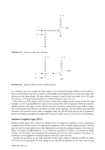
FIGURE 40.21 Diode–transistor logic NOR gate.
+V +V
(A.B)'
A
B
FIGURE 40.22 Improved diode–transistor NAND logic gate.
In a transistor npn, for example, the base–emitter is forward biased during conduction and collector–
base is reverse biased. If we have a transistor with multiple emitter leads, then we can use the emitter–base
junction for the input diodes. The base–collector junction is used for the base-diode in the DTL gate.
The result is a TTL gate implementation of a NAND function in Fig. 40.23 [4].
Here, when any of the inputs is LOW, the base–emitter loop conducts and the emitter of the first stage
transistor is at 0.2 V, giving HIGH for output at the inverter. When all the inputs are HIGH, the transistor
multiple emitters (first stage) is cutoff. Therefore, all other transistors conduct with a logic LOW at output.
The manufacturer’s data sheet for each device provides circuit diagrams, and all technical data including
maximum and minimum input values, propagation delay, rise and fall times, fan-out, fan-in limitations,
power consumption, and application suggestions. These are excellent sources of information for the designer.
Emitter-Coupled Logic (ECL)
Emitter-coupled logic (ECL) devices are bipolar devices in which the transistor is never saturated or
completely shut off. The result is very high speed compared to TTL or CMOS implementations. The ECL
gates are used in several applications where high speed is essential, for example, computer cache memory.
Figure 40.24 shows a NOR/OR gate [5]. V CC is connected to ground (0 V) while V EE is connected to supply
voltage, -5.2 V for better noise immunity. The transition time from one state to another is less than 1 ns,
resulting in several gigahertz operating frequency when ECL gates are used.
Because the transistors are not fully saturated, the ECL gates output at HIGH and LOW are about
–0.75 and –1.6 V, respectively. The bias voltage is set at the base of transistor Q 4 , the value is the average
©2002 CRC Press LLC