Page 1108 - The Mechatronics Handbook
P. 1108

1
                                           CLK/I
                                                              Increment
                                          First   0  4  8  12  16  20  24  28  32  36  40    Asynchronous Reset
                                          Fuse  0                                            (to all registers)
                                          Numbers
                                                                                     Macro-  23
                                                                                     cell    I/O/Q
                                               396
                                                                                     P=5808
                                                                                     R=5809
                                               440
                                                                                     Macro-  22
                                                                                     cell    I/O/Q
                                               880
                                              2                                      P=5810
                                                                                     R=5811
                                               924
                                                                                     Macro-  21
                                                                                     cell    I/O/Q
                                              1452
                                              3                                      P=5812
                                                                                     R=5813
                                              1496
                                                                                     Macro-  20
                                                                                     cell    I/O/Q
                                              2112
                                              4                                      P=5814
                                                                                     R=5815
                                              2156
                                                                                     Macro-  19
                                                                                     cell    I/O/Q
                                              2860
                                              5                                      P=5816
                                                                                     R=5817
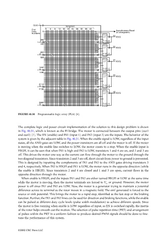
                                 FIGURE 40.30  Programmable logic array (PLA) [6].


                                 The complete logic and power circuit implementation of the solution to this design problem is shown
                                 in Fig. 40.31, which is known as the H-bridge. The motor is connected between the output pins (out1
                                 and out2) [7]. The EN (enable) and IN1 (input 1) and IN2 (input 2) are the inputs. The behavior of the
                                 system is given by the adjacent table in Fig. 40.31. When the enable signal is LOW, regardless of the input
                                 states, all the AND gates are LOW, and the power transistors are all off and the motor is off. If the motor
                                 is moving when the enable line switches to LOW, the motor coasts to a stop. When the enable input is
                                 HIGH, it can be seen that when IN1 is high and IN2 is LOW, transistors 1 and 4 are on, and 2 and 3 are
                                 off. This drives the motor one way as the current can flow through the motor to the ground through the
                                 two diagonal transistors. Since transistors 2 and 3 are off, short circuit from power to ground is prevented.
                                 This is designed by inputting the complements of IN1 and IN2 to the AND gates driving transistors 3
                                 and 4, respectively. When IN2 is HIGH and IN1 is LOW, the motor runs in the opposite direction (while
                                 the enable is HIGH). Since transistors 2 and 4 are closed and 1 and 3 are open, current flows in the
                                 opposite direction through the motor.
                                   When enable is HIGH, and the inputs IN1 and IN2 are either turned HIGH or LOW at the same time
                                 while the motor is moving, then the motor terminals are forced to V cc  or ground. However, the motor
                                 power is off since IN1 and IN2 are LOW. Now, the motor is a generator trying to maintain a potential
                                 difference across its terminal as the rotor moves in a magnetic field. The emf generated is forced to the
                                 source or sink potential. This brings the motor to a rapid stop, identified as the fast stop or the braking
                                 function. Further, the IN1 and IN2 lines can be used for direction and braking functions, while the enable
                                 can be pulsed at different duty cycle levels (pulse width modulation) to achieve different speeds. Since
                                 the motor is free running when enable is LOW regardless of input, as EN is switched rapidly, the inertia
                                 of the rotor helps smooth out the motion. The selection of pulse repetition time (PRT) and arrangement
                                 of pulses within the PRT in a uniform fashion to produce desired PWM signals should be done to fine-
                                 tune the performance of this system.


                                 ©2002 CRC Press LLC
   1103   1104   1105   1106   1107   1108   1109   1110   1111   1112   1113