
Page 1113 - The Mechatronics Handbook
P. 1113
Design Steps
There are six simple design steps as follows:
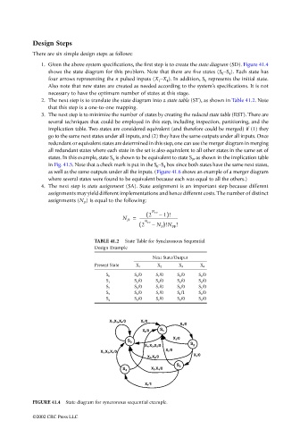
1. Given the above system specifications, the first step is to create the state diagram (SD). Figure 41.4
shows the state diagram for this problem. Note that there are five states (S 0 –S 4 ). Each state has
four arrows representing the n pulsed inputs (X 1 –X 4 ). In addition, S 0 represents the initial state.
Also note that new states are created as needed according to the system’s specifications. It is not
necessary to have the optimum number of states at this stage.
2. The next step is to translate the state diagram into a state table (ST), as shown in Table 41.2. Note
that this step is a one-to-one mapping.
3. The next step is to minimize the number of states by creating the reduced state table (RST). There are
several techniques that could be employed in this step, including inspection, partitioning, and the
implication table. Two states are considered equivalent (and therefore could be merged) if (1) they
go to the same next states under all inputs, and (2) they have the same outputs under all inputs. Once
redundant or equivalent states are determined in this step, one can use the merger diagram in merging
all redundant states where each state in the set is also equivalent to all other states in the same set of
states. In this example, state S 4 is shown to be equivalent to state S 0 , as shown in the implication table
in Fig. 41.5. Note that a check mark is put in the S 0 –S 4 box since both states have the same next states,
as well as the same outputs under all the inputs. (Figure 41.6 shows an example of a merger diagram
where several states were found to be equivalent because each was equal to all the others.)
4. The next step is state assignment (SA). State assignment is an important step because different
assignments may yield different implementations and hence different costs. The number of distinct
assignments (N D ) is equal to the following:
N FF
2 ( – 1)!
N D = ---------------------------------------
N
2 ( FF – N S )!N FF !
TABLE 41.2 State Table for Synchronous Sequential
Design Example
Next State/Output
Present State X 1 X 2 X 3 X 4
S 0 /0 S 1 /0 S 0 /0 S 0 /0
S 0
S 2 /0 S 0 /0 S 0 /0 S 0 /0
S 1
S 0 /0 S 1 /0 S 0 /0 S 3 /0
S 2
S 0 /0 S 1 /0 S 4 /1 S 0 /0
S 3
S 0 /0 S 1 /0 S 0 /0 S 0 /0
S 4
X 1 ,X 3 ,X 4 /0 X 2 /0
X 4 /0
X 2 /0 S 1
X 2 /0
S 0
X 1 ,X 2 ,X 3 /0 S 2
X 2 /0
X 1 ,X 3 ,X 4 /0
X 3 /0
X 1 ,X 4 /0
S 3
X 3 ,X 4 /0
S 4
X 1 /1
FIGURE 41.4 State diagram for syncronous sequential example.
©2002 CRC Press LLC