
Page 1116 - The Mechatronics Handbook
P. 1116
41.3 Asynchronous Sequential System Synthesis
Synchronous sequential circuits operate with clocks that control the total operation of the system. Such
synchronous sequential circuits are called to operate in a pulse mode behavior. On the other hand, in an
asynchronous sequential system, changes in the state of the system are not triggered by clock pulses.
Instead, changes in the state of the system depend on changes in the primary inputs. However, since a
good and reliable design requires the primary inputs to the circuit to change only one at a time, then
such changes must allow enough time to elapse in order to reach a stable state. A stable state is achieved
when all internal elements no longer change their values. A circuit that adheres to this behavior is called
a fundamental mode circuit.
A main advantage of asynchronous circuits is their speed of operation. Since there is no clock (which
must be at least as long as the slowest path in the circuit), the speed would be equal to the propagation
path delay in the local portion of the circuit. Hence, the performance of the overall system could be
enhanced. However, the major disadvantages of the asynchronous system are races and hazards, both
static and dynamic. These race conditions and hazards make asynchronous circuits more difficult to deal
with, and hence, they must be designed with care.
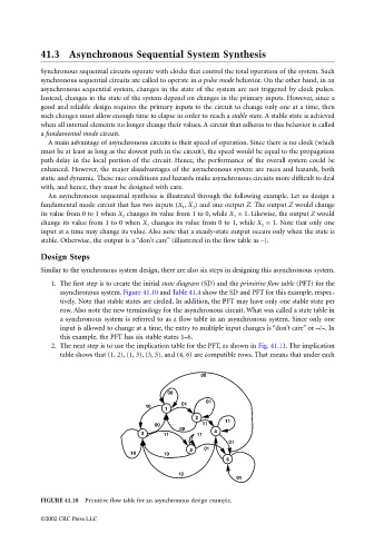
An asynchronous sequential synthesis is illustrated through the following example. Let us design a
fundamental mode circuit that has two inputs (X 1 , X 2 ) and one output Z. The output Z would change
its value from 0 to 1 when X 2 changes its value from 1 to 0, while X 1 = 1. Likewise, the output Z would
change its value from 1 to 0 when X 1 changes its value from 0 to 1, while X 2 = 1. Note that only one
input at a time may change its value. Also note that a steady-state output occurs only when the state is
stable. Otherwise, the output is a “don’t care” (illustrated in the flow table as –).
Design Steps
Similar to the synchronous system design, there are also six steps in designing this asynchronous system.
1. The first step is to create the initial state diagram (SD) and the primitive flow table (PFT) for the
asynchronous system. Figure 41.10 and Table 41.4 show the SD and PFT for this example, respec-
tively. Note that stable states are circled. In addition, the PFT may have only one stable state per
row. Also note the new terminology for the asynchronous circuit. What was called a state table in
a synchronous system is referred to as a flow table in an asynchronous system. Since only one
input is allowed to change at a time, the entry to multiple input changes is “don’t care” or –/–. In
this example, the PFT has six stable states 1–6.
2. The next step is to use the implication table for the PFT, as shown in Fig. 41.11. The implication
table shows that (1, 2), (1, 3), (3, 5), and (4, 6) are compatible rows. That means that under each
00
00
01
01
10
1
2
11
00 11
00
3 11 11 4
01
01
5
10 10
6
10
01
FIGURE 41.10 Primitive flow table for an asynchronous design example.
©2002 CRC Press LLC