Page 1115 - The Mechatronics Handbook
P. 1115

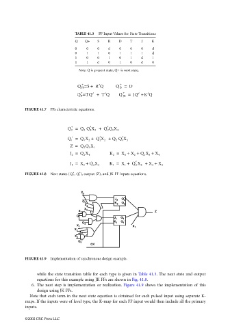
TABLE 41.3  FF Input Values for State Transitions
                                                       Q    Q+   S    R    D   T    J    K
                                                       0    0    0    d    0    0   0    d
                                                       0    1    1    0    1    1   1    d
                                                       1    0    0    1    0    1   d    1
                                                       1    1    d    0    1    0   d    0
                                                         Note: Q is present state, Q+ is next state.


                                                          +
                                                                           +
                                                           =
                                                        Q SR S +  R′Q    Q D =  D
                                                          +                 +
                                                           =
                                                        Q T TQ′ +  T′Q     Q JK =  JQ′ + K′Q
                                 FIGURE 41.7  FFs characteristic equations.


                                                              ′
                                                                     ′
                                                      +
                                                    Q 2 =  Q 2  Q 1 X 3 +   Q 2 Q 1 X 4
                                                      +           ′         ′
                                                    Q 1 =  Q 1 X 2 +   Q 2 X 2 +  Q 2  Q 1 X 3
                                                     Z =  Q 2 Q 1 X 1
                                                     J 2 =  Q 1 X 4   K 2 =  X 1 +  X 2 +  Q 1 X 3 +  X 4
                                                                                  ′
                                                     J 1 =  X 2 +  Q X 3  K 1 =  X 1 +   Q 2 X 2 +  X 3 +  X 4
                                                               2
                                                      +
                                                         +
                                 FIGURE 41.8  Next states (Q 2 , Q 1 ) , output (Z), and JK FF inputs equations.


                                                          X 4
                                                                         J 2  Q 2
                                                          Q 1
                                                                         K 2  Q 2
                                                            X 1
                                                           X 2
                                                                                          Z
                                                         X 3
                                                        Q
                                                                        J 1  Q 1
                                                                           Q 1 '
                                                                        K 1
                                                          Q 2
                                                        X 1
                                                                                X 1
                                                       X 3
                                                         X 4
                                                       X 2
                                                         Q 2 '
                                                              CK
                                 FIGURE 41.9  Implementation of synchronous design example.
                                       while the state transition table for each type is given in Table 41.3. The next state and output
                                       equations for this example using JK FFs are shown in Fig. 41.8.
                                    6.  The next step is implementation or  realization.  Figure 41.9 shows the implementation of  this
                                       design using JK FFs.
                                   Note that each term in the next state equation is obtained for each pulsed input using separate K-
                                 maps. If the inputs were of level type, the K-map for each FF input would then include all the primary
                                 inputs.

                                 ©2002 CRC Press LLC
   1110   1111   1112   1113   1114   1115   1116   1117   1118   1119   1120