
Page 1118 - The Mechatronics Handbook
P. 1118
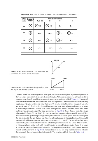
TABLE 41.6 Flow Table (FT) with an Added Cycle D to Eliminate A Critical Race

                                              State  Present            Next State / Output
                                             Assign-
                                              ment  State    X 2X 1  00  01        11           10
                                                     A      A  / 0     A  / 0      C / -       B / -
                                              00

                                              01     B       A / -      D / -     B  / 1     B  / 0


                                              10     C       A / -     C  / 1     C / 0        B / -


                                              11     D        - / -      C / -     - / -       - / -


                                                                              00,10
                                                                           A            B

                                                                           11
                                                                                  01
                                 FIGURE 41.12  State transition.  AB transitions are
                                 noncritical; AC, BC are critical transitions.  C

                                                                           A(00)        B(01)


                                 FIGURE 41.13  State transitions through cycle D. Note
                                 that B goes to C through cycle D.        C(10)      D(11)

                                    3. The next step is the state assignment. Here again, each state must be given adjacent assignments if
                                       there is a state transition between any two stable states. As long as there are more than two stable
                                       states per row, then all transitions between the states are considered critical. Figure 41.12 shows all
                                       critical transitions between the stable states. Each line represents a transition with its corresponding
                                       input value indicated on the line. Note that input 00 is not a critical transition because it has only
                                       one stable state (A). But if a critical transition exists, we must have adjacent assignments in order
                                       to avoid the problem of a critical race, where we might end up in a different stable state when
                                       multiple input changes occur. Our state assignment in Fig. 41.12 shows that we must have three
                                       adjacencies (A, B), (A, C), and (B, C). But since we can have only two adjacencies with two variables,
                                       then we can either give multiple assignments per stable state or create cycles. The disadvantage of
                                       the first method is the fact that we may have more logic because of the added states, which would
                                       consequently add to the cost and reduce the performance (i.e., speed.) The second method is the
                                       creation of cycles. This method would also affect the performance with the added delay of cycles.
                                       In this example, an added cycle with no stable states is created between states B and C in order
                                       to ensure the transition between the two states. In this problem, state D is a cycle created between
                                       states B and C, as shown in Fig. 41.13. Hence, states B and C can only make transitions between
                                       them through the newly created cycle in state D. The new flow table is shown in Table 41.6.

                                 ©2002 CRC Press LLC