Page 1117 - The Mechatronics Handbook
P. 1117

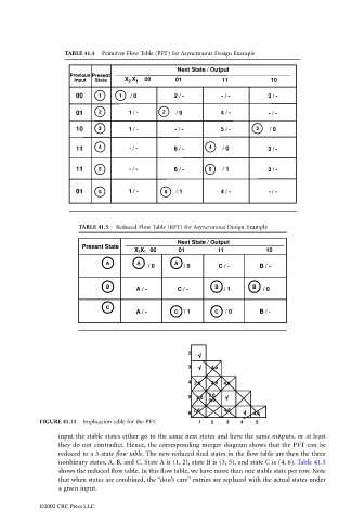
TABLE 41.4  Primitive Flow Table (PFT) for Asyncronous Design Example

                                                                        Next State / Output
                                          Previous Present
                                           Input  State  X X 1  00     01           11           10
                                                          2
                                           00     1    1  / 0          2 / -        - / -        3 / -

                                           01     2       1 / -    2   / 0          4 / -        - / -

                                           10     3       1 / -        - / -        5 / -    3   / 0

                                           11     4       - / -        6 / -    4   / 0          3 / -


                                           11     5       - / -        6 / -    5   / 1          3 / -


                                           01     6       1 / -     6  / 1          4 / -        - / -


                                            TABLE 41.5  Reduced Flow Table (RFT) for Asyncronous Design Example
                                                                        Next State / Output
                                             Present State
                                                            X 2X 1  00  01         11           10
                                                    A       A          A
                                                               / 0       / 0       C / -      B / -

                                                    B       A / -       C / -     B  / 1    B  / 0


                                                    C
                                                            A / -      C  / 1     C  / 0      B / -


                                                                           2
                                                                           3     4,5

                                                                           4  2,6  2,6  4,5
                                                                           5  2,6  2,6
                                                                                4,5
                                                                            2,6     4,5
                                                                           6                 4,5
                                 FIGURE 41.11  Implication table for the PFT.  1  2  3   4   5
                                       input the stable states either go to the same next states and have the same outputs, or at least
                                       they do not contradict. Hence, the corresponding merger diagram shows that the PFT can be
                                       reduced to a 3-state flow table. The new reduced final states in the flow table are then the three
                                       nonbinary states, A, B, and C. State A is (1, 2), state B is (3, 5), and state C is (4, 6). Table 41.5
                                       shows the reduced flow table. In this flow table, we have more than one stable state per row. Note
                                       that when states are combined, the “don’t care” entries are replaced with the actual states under
                                       a given input.

                                 ©2002 CRC Press LLC
   1112   1113   1114   1115   1116   1117   1118   1119   1120   1121   1122