Page 1112 - The Mechatronics Handbook
P. 1112
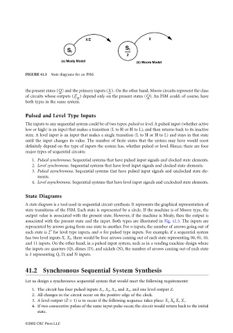
X/Z                         X
                                                                             S
                                                   S i                        i
                                                                             Z
                                                 (a) Mealy Model
                                                                                 (b) Moore Model

                                 FIGURE 41.3  State diagrams for an FSM.


                                 the present states (Q)  and the primary inputs (X).  On the other hand, Moore circuits represent the class
                                 of circuits whose outputs (Z )  depend only on the present states (Q) . An FSM could, of course, have
                                                        M
                                 both types in the same system.

                                 Pulsed and Level Type Inputs
                                 The inputs to any sequential system could be of two types: pulsed or level. A pulsed input (whether active
                                 low or high) is an input that makes a transition (L to H or H to L), and then returns back to its inactive
                                 state. A level input is an input that makes a single transition (L to H or H to L) and stays in that state
                                 until the input changes its value. The number of finite states that the system may have would most
                                 definitely depend on the type of inputs the system has, whether pulsed or level. Hence, there are four
                                 major types of sequential circuits:

                                    1. Pulsed synchronous. Sequential systems that have pulsed input signals and clocked state elements.
                                    2. Level synchronous. Sequential systems that have level input signals and clocked state elements.
                                    3. Pulsed asynchronous. Sequential systems that have pulsed input signals and unclocked state ele-
                                       ments.
                                    4. Level asynchronous. Sequential systems that have level input signals and unclocked state elements.

                                 State Diagrams

                                 A state diagram is a tool used in sequential circuit synthesis. It represents the graphical representation of
                                 state transitions of the FSM. Each state is represented by a circle. If the machine is of Moore type, the
                                 output value is associated with the present state. However, if the machine is Mealy, then the output is
                                 associated with the present state and the input. Both types are illustrated in Fig. 41.3. The inputs are
                                 represented by arrows going from one state to another. For n inputs, the number of arrows going out of
                                            n
                                 each state is 2  for level type inputs, and n for pulsed type inputs. For example, if a sequential system
                                 has two level inputs X 1  X 2 , there would be four arrows coming out of each state representing 00, 01, 10,
                                 and 11 inputs. On the other hand, in a pulsed input system, such as in a vending machine design where
                                 the inputs are quarters (Q), dimes (D), and nickels (N), the number of arrows coming out of each state
                                 is 3 representing Q, D, and N inputs.


                                 41.2 Synchronous Sequential System Synthesis


                                 Let us design a synchronous sequential system that would meet the following requirements:
                                    1. The circuit has four pulsed inputs X 1 , X 2 , X 3 , and X 4 , and one level output Z.
                                    2. All changes in the circuit occur on the positive edge of the clock.
                                    3. A level output (Z = 1) is to occur if the following sequence takes place: X 2  X 4  X 3  X 1 .
                                    4. If two consecutive pulses of the same input pulse occur, the circuit would return back to the initial
                                       state.

                                 ©2002 CRC Press LLC

