Page 1111 - The Mechatronics Handbook
P. 1111

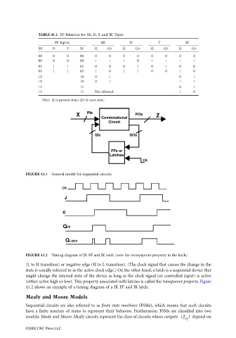
TABLE 41.1 FF Behavior for SR, D, T, and JK Types
                                              FF Inputs           SR          D           T           JK
                                       SR    D     T     JK    Q    Q+     Q    Q+     Q    Q+     Q    Q+
                                       00    0     0     00    0     0     0     0     0     0     0     0
                                       00    0     0     00    1     1     1     0     1     1     1     1
                                       01    1     1     01    0     0     0     1     0     1     0     0
                                       01    1     1     01    1     0     1     1     0     0     1     0
                                       10                10    0     1                             0     1
                                       10                10    0     1                             1     1
                                       11                11                                        0     1
                                       11                11    Not allowed                         1     0
                                        Note: Q is present state, Q+ is next state.


                                                       X    PIs                 POs      Z
                                                                  Combinational
                                                                     Circuit


                                                               SIs            SOs


                                                                      FFs or
                                                                     Latchea
                                                                                   CK


                                 FIGURE 41.1  General model for sequential circuits.


                                                 CK
                                                  J


                                                 K


                                                 QFF


                                                  QLatch


                                 FIGURE 41.2  Timing diagram of JK FF and JK latch (note the transpaprent property in the latch).
                                 (L to H transition) or negative edge (H to L transition). (The clock signal that causes the change in the
                                 state is usually referred to as the active clock edge.) On the other hand, a latch is a sequential device that
                                 might change the internal state of the device as long as the clock signal (or controlled input) is active
                                 (either active high or low). This property associated with latches is called the transparent property. Figure
                                 41.2 shows an example of a timing diagram of a JK FF and JK latch.
                                 Mealy and Moore Models

                                 Sequential circuits are also referred to as finite state machines (FSMs), which means that such circuits
                                 have a finite number of states to represent their behavior. Furthermore, FSMs are classified into two
                                 models: Mealy and Moore. Mealy circuits represent the class of circuits whose outputs  (Z )   depend on
                                                                                                      m
                                 ©2002 CRC Press LLC
   1106   1107   1108   1109   1110   1111   1112   1113   1114   1115   1116