
Page 1109 - The Mechatronics Handbook
P. 1109
100nF
D1 D2
M
D3 D4
+V s
Out1 Out2
2 3 4
9
1 2
5
In 1 3 4
7
In 2
6
EnA
1 8
SENSE A R s A
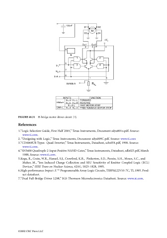
INPUTS FUNCTION
=L FORWARD
In 1 =H In 2
ENA=H =H REVERSE
In 1 =L In 2
FAST MOTOR STOP
In 1 =In 2
ENA=L In 1 =X In 2 =X FREE RUNNING MOTOR STOP
FIGURE 40.31 H-bridge motor driver circuit [7].
References
1. “Logic Selection Guide, First Half 2001,” Texas Instruments, Document sdyu001o.pdf. Source:
www.ti.com.
2. “Designing with Logic,” Texas Instruments, Document sdya009C.pdf. Source: www.ti.com
3.“CD4069UB Types- Quad-Inverter,” Texas Instruments, Datasheet, schs054.pdf, 1998. Source:
www.ti.com.
4.“SN5400 Quadruple 2-Input Positive NAND-Gates,” Texas Instruments, Datasheet, sdls025.pdf, March
1988, Source: www.ti.com.
5.Koga, R., Crain, W.R., Hansel, S.J., Crawford, K.B., Pinkerton, S.D., Peozin, S.H., Moses, S.C., and
Maher, M., “Ion Induced Charge Collection and SEU Sensitivity of Emitter Coupled Logic (ECL)
Devices,” IEEE Trans on Nuclear Science, 42(6), 1823–1828, 1995.
6.High-performance Impact-X ™ Programmable Array Logic Circuits, TIBPAL22V10-7C, TI, 1995. Prod-
uct datasheet.
7.“Dual Full-Bridge Driver L298,” SGS Thomson Microelectronics Datasheet. Source: www.st.com.
©2002 CRC Press LLC