
Page 1120 - The Mechatronics Handbook
P. 1120
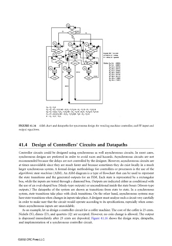
FIGURE 41.16  ASM chart and datapaths for syncronous design for vending machine controller, and FF input and
                                 output equations.


                                 41.4 Design of Controllers’ Circuits and Datapaths

                                 Controller circuits could be designed using synchronous as well asynchronous circuits. In most cases,
                                 synchronous designs are preferred in order to avoid races and hazards. Asynchronous circuits are not
                                 recommended because the delays are not controlled by the designer. However, asynchronous circuits are
                                 at times unavoidable since they are much faster and because sometimes they do exist locally in a much
                                 larger synchronous system. A formal design methodology for controllers or processors is the use of the
                                 algorithmic state machines (ASM). An ASM diagram is a type of flowchart that can be used to represent
                                 the state transitions and the generated outputs for an FSM. Each state is represented by a rectangular
                                 box, while the inputs are tested through a diamond box. Outputs are indicated either as conditional with
                                 the use of an oval-shaped box (Mealy-type outputs) or unconditional inside the state boxes (Moore-type
                                 outputs.) The datapaths of the system are shown as transitions from state to state. In a synchronous
                                 system, state transitions take place with clock transitions. On the other hand, asynchronous systems may
                                 have state transitions when changes in inputs take place. A designer must analyze such a circuit very carefully
                                 in order to make sure that the circuit would operate according to its specifications, especially when some-
                                 times asynchronous inputs are unavoidable.
                                   As an example, let us design a controller circuit for a coffee machine. The cost of the coffee is 25 cents.
                                 Nickels (N), dimes (D), and quarters (Q) are accepted. However, no coin change is allowed. The output
                                 is dispensed immediately after 25 cents are deposited. Figure 41.16 shows the design steps, datapaths,
                                 and implementation of a synchronous controller circuit.


                                 ©2002 CRC Press LLC