
Page 1099 - The Mechatronics Handbook
P. 1099
0066_Frame_C40 Page 9 Wednesday, January 9, 2002 8:21 PM
INPUTS OUTPUT
A B C X
0 0 0 1
0 1 0 1
1 0 0 0
1 1 0 1
0 0 1 0
0 1 1 1
1 0 1 0
1 1 1 0
FIGURE 40.15 Truth table for a logic circuit design and minimization.
1
AB
2
C 00 01 11 10
0 1 1 1 0
1 0 1 0 0
3
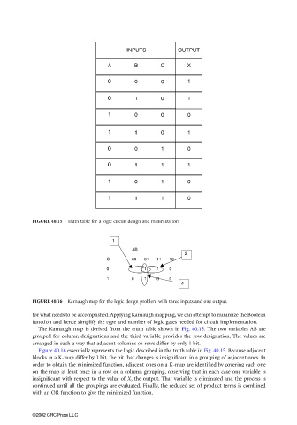
FIGURE 40.16 Karnaugh map for the logic design problem with three inputs and one output.
for what needs to be accomplished. Applying Karnaugh mapping, we can attempt to minimize the Boolean
function and hence simplify the type and number of logic gates needed for circuit implementation.
The Karnaugh map is derived from the truth table shown in Fig. 40.15. The two variables AB are
grouped for column designations and the third variable provides the row designation. The values are
arranged in such a way that adjacent columns or rows differ by only 1 bit.
Figure 40.16 essentially represents the logic described in the truth table in Fig. 40.15. Because adjacent
blocks in a K-map differ by 1 bit, the bit that changes is insignificant in a grouping of adjacent ones. In
order to obtain the minimized function, adjacent ones on a K-map are identified by covering each one
on the map at least once in a row or a column grouping, observing that in each case one variable is
insignificant with respect to the value of X, the output. That variable is eliminated and the process is
continued until all the groupings are evaluated. Finally, the reduced set of product terms is combined
with an OR function to give the minimized function.
©2002 CRC Press LLC