
Page 1181 - The Mechatronics Handbook
P. 1181
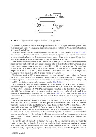
VOLTAGE
                                                                      FOLLOWER  −
                                                                                +
                                                                                     OUTPUT


                                                        INPUT     RTD             CONSTANT
                                                                                  CURRENT
                                                                                  SOURCE


                                 FIGURE 45.22  Typical resistance temperature detector (RTD) application.

                                 The first two requirements are met by appropriate construction of the signal conditioning circuit. The
                                 third requirement is met by using a reference temperature sensor, probably an IC temperature transducer
                                 of the type described later.
                                   Thermocouple and thermocouple accessories are fabricated for a variety of applications [Fig. 45.21(b)].
                                 Protective shields (thermowells) are used to protect thermocouple junctions in corrosive environments
                                 or where conducting liquids can short circuit the thermocouple voltage; however, exposed (bare) junc-
                                 tions are used wherever possible, particularly when a fast response is essential.
                                   Resistance temperature detectors (RTD) are based on the principle that the electrical resistivity of most
                                 metals increases predictably with temperature. Platinum is the preferred metal for RTDs, although other
                                 less expensive metals are used in some applications. The resistivity of platinum is one of the standards
                                 by which temperature is measured. The relatively good linearity of the resistivity of platinum over a wide
                                 temperature  range (-200  to 800°C) makes platinum  RTDs  suitable for stable,  accurate  temperature
                                 transducers, which are easily adapted to control systems applications.
                                   The disadvantage of the RTD is that the temperature-sensitive element is a rather fragile metal filament
                                 wound on a ceramic bobbin or a thin metal film deposited on a ceramic substrate. RTD elements are
                                 usually encapsulated and are rarely used as bare elements. The accessories and application packages used
                                 with RTDs are similar to those used with thermocouples [Fig. 45.21(b)].
                                   Most platinum RTDs are fabricated so as to have a nominal resistance of 100 W at 0°C. The resistance
                                 temperature coefficient of platinum is approximately 3–4 mW/W/°C, so resolution of the temperature
                                 to within 1°C for a nominal 100-W RTD element requires resolution of the absolute resistance within
                                 0.3–0.4 W. These resistance resolution requirements dictate use of special signal conditioning techniques
                                 to cancel the lead and contact resistance of the RTD element (Fig. 45.22). The circuit depicted in Fig. 45.22
                                 is a variation of a 4-wire ohmmeter. Most RTDs are manufactured with four leads to be compatible with
                                 such circuits.
                                   Thermistors are specially prepared metal oxide semiconductors that exhibit a strong negative temper-
                                 ature coefficient, in sharp contrast to the weak positive temperature coefficient of RTDs. Nominal
                                 thermistor resistance, usually specified for 25°C, ranges from less than 1000 W to more than 1 MW,
                                 with sensitivities greater than 100 W/°C. Thus, the thermistor is the basis for temperature sensors that
                                 are much more sensitive and require less special signal conditioning than either thermocouples or RTDs.
                                 The tradeoff is the marked nonlinearity of the resistance-temperature characteristic. To minimize this
                                 problem, manufacturers provide packages in which the thermistor has been connected into a resistor
                                 network chosen to provide a relatively linear resistance-temperature characteristic over a nominal tem-
                                 perature range.
                                   The development of thermistor technology has lead to the IC temperature sensor in which the
                                 temperature-sensitive junction(s) and the required signal conditioning circuits are provided in a mono-
                                 lithic package. The user is only required to provide a supply voltage (typically 5 V DC) to the IC in order
                                 to obtain an analog output voltage proportional to temperature. Thermistors and IC temperature sensors


                                 ©2002 CRC Press LLC