
Page 1182 - The Mechatronics Handbook
P. 1182
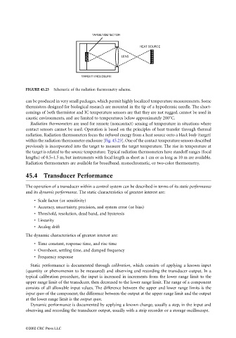
TARGET/DETECTOR

                                                                                  HEAT SOURCE

                                                                          LENS


                                                         TARGET ENCLOSURE

                                 FIGURE 45.23  Schematic of the radiation thermometry scheme.

                                 can be produced in very small packages, which permit highly localized temperature measurements. Some
                                 thermistors designed for biological research are mounted in the tip of a hypodermic needle. The short-
                                 comings of both thermistor and IC temperature sensors are that they are not rugged, cannot be used in
                                 caustic environments, and are limited to temperatures below approximately 200°C.
                                   Radiation thermometers are used for remote (noncontact) sensing of temperature in situations where
                                 contact sensors cannot be used. Operation is based on the principles of heat transfer through thermal
                                 radiation. Radiation thermometers focus the infrared energy from a heat source onto a black body (target)
                                 within the radiation thermometer enclosure [Fig. 45.23]. One of the contact temperature sensors described
                                 previously is incorporated into the target to measure the target temperature. The rise in temperature at
                                 the target is related to the source temperature. Typical radiation thermometers have standoff ranges (focal
                                 lengths) of 0.5–1.5 m, but instruments with focal length as short as 1 cm or as long as 10 m are available.
                                 Radiation thermometers are available for broadband, monochromatic, or two-color thermometry.

                                 45.4 Transducer Performance

                                 The operation of a transducer within a control system can be described in terms of its static performance
                                 and its dynamic performance. The static characteristics of greatest interest are:
                                     • Scale factor (or sensitivity)
                                     • Accuracy, uncertainty, precision, and system error (or bias)
                                     • Threshold, resolution, dead band, and hysteresis
                                     • Linearity
                                     • Analog drift
                                 The dynamic characteristics of greatest interest are:
                                     • Time constant, response time, and rise time
                                     • Overshoot, settling time, and damped frequency
                                     • Frequency response
                                   Static performance is documented through  calibration, which consists of applying a known input
                                 (quantity or phenomenon to be measured) and observing and recording the transducer output. In a
                                 typical calibration procedure, the input is increased in increments from the lower range limit to the
                                 upper range limit of the transducer, then decreased to the lower range limit. The range of a component
                                 consists of all allowable input values. The difference between the upper and lower range limits is the
                                 input span of the component; the difference between the output at the upper range limit and the output
                                 at the lower range limit is the output span.
                                   Dynamic performance is documented by applying a known change, usually a step, in the input and
                                 observing and recording the transducer output, usually with a strip recorder or a storage oscilloscope.


                                 ©2002 CRC Press LLC