Page 1180 - The Mechatronics Handbook
P. 1180

BIMETALLIC
                                                                 ELEMENT


                                                                                       ELECTRICAL
                                                                                       CONTACT


                                 FIGURE 45.20  Bimetallic thermal switch.

                                                                   ISOTHERMAL TERMINAL BLOCK


                                                                                SIGNAL
                                           INPUT    THERMOCOUPLE                CONDITIONING  OUTPUT
                                                                                CIRCUIT
                                                                                TEMPERATURE
                                                                                CORRECTIONS
                                                    TERMINAL BLOCK
                                        (a)         TEMPERATURE SENSOR
                                                                                    MOUNTING     ENCAPSULATED
                                                                                    HOLE         JUNCTION


                                           THREADED WELL                        SCREW-MOUNT
                                                        MOUNTING HOLE


                                       (b)     FLANGED WELL                           ADHESIVE PAD

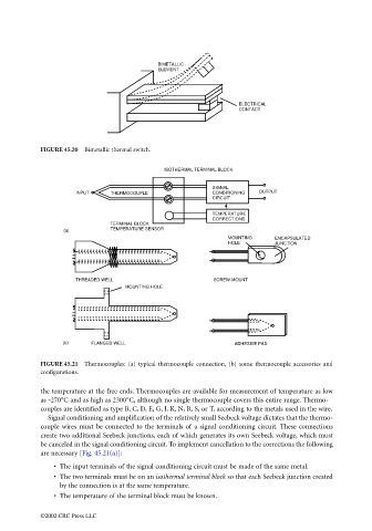
                                 FIGURE 45.21  Thermocouples: (a) typical thermocouple connection, (b) some thermocouple accessories and
                                 configurations.

                                 the temperature at the free ends. Thermocouples are available for measurement of temperature as low
                                 as -270°C and as high as 2300°C, although no single thermocouple covers this entire range. Thermo-
                                 couples are identified as type B, C, D, E, G, J, K, N, R, S, or T, according to the metals used in the wire.
                                   Signal conditioning and amplification of the relatively small Seebeck voltage dictates that the thermo-
                                 couple wires must be connected to the terminals of a signal conditioning circuit. These connections
                                 create two additional Seebeck junctions, each of which generates its own Seebeck voltage, which must
                                 be canceled in the signal conditioning circuit. To implement cancellation to the corrections the following
                                 are necessary [Fig. 45.21(a)]:
                                     • The input terminals of the signal conditioning circuit must be made of the same metal.
                                     • The two terminals must be on an isothermal terminal block so that each Seebeck junction created
                                       by the connection is at the same temperature.
                                     • The temperature of the terminal block must be known.

                                 ©2002 CRC Press LLC
   1175   1176   1177   1178   1179   1180   1181   1182   1183   1184   1185