
Page 1175 - The Mechatronics Handbook
P. 1175
ULTRASOUND
TRANSMITTER
SOUND PATH
INPUT
FLUID FLOW
ULTRASOUND
RECEIVER
SYNCHRONIZATION
AND TIMING
TIMER OUTPUT
CONVERTER
(a)
PARTICLES
OR BUBBLES
INPUT
FLUID FLOW
TRANSMITTED/
REFLECTED
SOUND PATH
ULTRASOUND
TRANSRECEIVER
FREQUENCY
OUTPUT
SHIFT
(b) CONVERTER
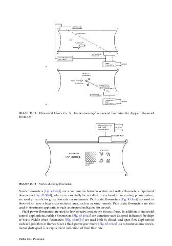
FIGURE 45.11 Ultrasound flowmeters: (a) Transmission-type ultrasound flowmeter, (b) doppler ultrasound
flowmeter.
FREQUENCY-TO-
VOLTAGE OUTPUT
CONVERTER
SOUND PICKUP
VORTICES
FLUID FLOW
INPUT
SHEDDING
BODY
FIGURE 45.12 Vortex-shedding flowmeter.
Nozzle flowmeters [Fig. 45.9(c)] are a compromise between venturi and orifice flowmeters. Pipe-bend
flowmeters [Fig. 45.9(d)], which can essentially be installed in any bend in an existing piping system,
are used primarily for gross flow rate measurements. Pitot-static flowmeters [Fig. 45.9(e)] are used in
flows which have a large cross-sectional area, such as in wind tunnels. Pitot-static flowmeters are also
used in freestream applications such as airspeed indicators for aircraft.
Fluid-power flowmeters are used in low-velocity, moderately viscous flows. In addition to industrial
control applications, turbine flowmeters [Fig. 45.10(a)] are sometime used as speed indicators for ships
or boats. Paddle wheel flowmeters [Fig. 45.10(b)] are used both in closed- and open-flow applications
such as liquid flow in flumes. Since a fluid-power gear motor [Fig. 45.10(c)] is a constant volume device,
motor shaft speed is always a direct indication of fluid flow rate.
©2002 CRC Press LLC