
Page 199 - The Mechatronics Handbook
P. 199
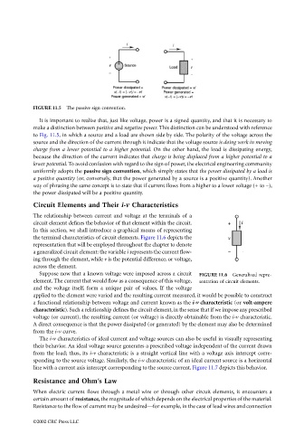
FIGURE 11.5  The passive sign convention.
                                   It is important to realize that, just like voltage, power is a signed quantity, and that it is necessary to
                                 make a distinction between positive and negative power. This distinction can be understood with reference
                                 to Fig. 11.5, in which a source and a load are shown side by side. The polarity of the voltage across the
                                 source and the direction of the current through it indicate that the voltage source is doing work in moving
                                 charge from a lower potential to a higher potential. On the other hand, the load is dissipating energy,
                                 because the direction of the current indicates that charge is being displaced from a higher potential to a
                                 lower potential. To avoid confusion with regard to the sign of power, the electrical engineering community
                                 uniformly adopts the passive sign convention, which simply states that the power dissipated by a load is
                                 a positive quantity (or, conversely, that the power generated by a source is a positive quantity). Another
                                 way of phrasing the same concept is to state that if current flows from a higher to a lower voltage (+ to –),
                                 the power dissipated will be a positive quantity.
                                 Circuit Elements and Their i-v Characteristics
                                 The relationship between current and voltage at the terminals of a
                                 circuit element defines the behavior of that element within the circuit.
                                 In this section, we shall introduce a graphical means of representing
                                 the terminal characteristics of circuit elements. Figure 11.6 depicts the
                                 representation that will be employed throughout the chapter to denote
                                 a generalized circuit element: the variable i represents the current flow-
                                 ing through the element, while v is the potential difference, or voltage,
                                 across the element.
                                   Suppose now that a known voltage were imposed across a circuit  FIGURE 11.6  Generalized repre-
                                 element. The current that would flow as a consequence of this voltage,  sentation of circuit elements.
                                 and the voltage itself, form a unique pair of values. If the voltage
                                 applied to the element were varied and the resulting current measured, it would be possible to construct
                                 a functional relationship between voltage and current known as the i-v characteristic (or volt-ampere
                                 characteristic). Such a relationship defines the circuit element, in the sense that if we impose any prescribed
                                 voltage (or current), the resulting current (or voltage) is directly obtainable from the i-v characteristic.
                                 A direct consequence is that the power dissipated (or generated) by the element may also be determined
                                 from the i-v curve.
                                   The i-v characteristics of ideal current and voltage sources can also be useful in visually representing
                                 their behavior. An ideal voltage source generates a prescribed voltage independent of the current drawn
                                 from the load; thus, its i-v characteristic is a straight vertical line with a voltage axis intercept corre-
                                 sponding to the source voltage. Similarly, the i-v characteristic of an ideal current source is a horizontal
                                 line with a current axis intercept corresponding to the source current. Figure 11.7 depicts this behavior.
                                 Resistance and Ohm’s Law

                                 When electric current flows through a metal wire or through other circuit elements, it encounters a
                                 certain amount of resistance, the magnitude of which depends on the electrical properties of the material.
                                 Resistance to the flow of current may be undesired—for example, in the case of lead wires and connection

                                 ©2002 CRC Press LLC