
Page 202 - The Mechatronics Handbook
P. 202
0066_Frame_C11 Page 8 Wednesday, January 9, 2002 4:14 PM
In addition to the resistance in ohms, the maximum allowable power dissipation (or power rating)
is typically specified for commercial resistors. Exceeding this power rating leads to overheating and can
cause the resistor to literally start on fire. For a resistor R, the power dissipated is given by
2
P = VI = I R = V (11.15)
2
-----
R
That is, the power dissipated by a resistor is proportional to the square of the current flowing through
it, as well as the square of the voltage across it. The following example illustrates a common engineering
application of resistive elements: the resistance strain gauge.
Example 11.1 Resistance Strain Gauges
A common application of the resistance concept to engineering measurements is the resistance strain
gauge. Strain gauges are devices that are bonded to the surface of an object, and whose resistance varies
as a function of the surface strain experienced by the object. Strain gauges may be used to perform
measurements of strain, stress, force, torque, and pressure. Recall that the resistance of a cylindrical
conductor of cross-sectional area A, length L, and conductivity σ is given by the expression
L
R = -------
sA
If the conductor is compressed or elongated as a consequence of an external force, its dimensions will
change, and with them its resistance. In particular, if the conductor is stretched, its cross-sectional area
will decrease and the resistance will increase. If the conductor is compressed, its resistance decreases,
since the length, L, will decrease. The relationship between change in resistance and change in length is
given by the gauge factor, G, defined by
G = ∆R/R
-------------
∆L/L
and since the strain ε is defined as the fractional change in length of an object by the formula
e = ∆L
-------
L
the change in resistance due to an applied strain ε is given by the expression
∆R = R 0 Ge
where R 0 is the resistance of the strain gauge under no strain and is called the zero strain resistance. The
value of G for resistance strain gauges made of metal foil is usually about 2.
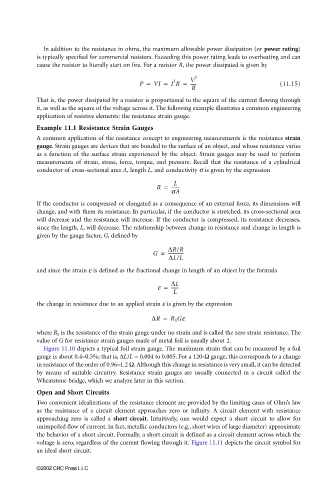
Figure 11.10 depicts a typical foil strain gauge. The maximum strain that can be measured by a foil
gauge is about 0.4–0.5%; that is, ∆L/L = 0.004 to 0.005. For a 120-Ω gauge, this corresponds to a change
in resistance of the order of 0.96–1.2 Ω. Although this change in resistance is very small, it can be detected
by means of suitable circuitry. Resistance strain gauges are usually connected in a circuit called the
Wheatstone bridge, which we analyze later in this section.
Open and Short Circuits
Two convenient idealizations of the resistance element are provided by the limiting cases of Ohm’s law
as the resistance of a circuit element approaches zero or infinity. A circuit element with resistance
approaching zero is called a short circuit. Intuitively, one would expect a short circuit to allow for
unimpeded flow of current. In fact, metallic conductors (e.g., short wires of large diameter) approximate
the behavior of a short circuit. Formally, a short circuit is defined as a circuit element across which the
voltage is zero, regardless of the current flowing through it. Figure 11.11 depicts the circuit symbol for
an ideal short circuit.
©2002 CRC Press LLC