
Page 205 - The Mechatronics Handbook
P. 205
0066_Frame_C11 Page 11 Wednesday, January 9, 2002 4:14 PM
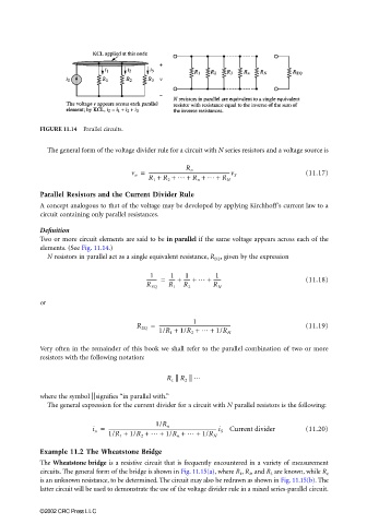
FIGURE 11.14 Parallel circuits.
The general form of the voltage divider rule for a circuit with N series resistors and a voltage source is
v n = R n (11.17)
R 1 + R 2 + … + R n + … + R N
-------------------------------------------------------------------v S
Parallel Resistors and the Current Divider Rule
A concept analogous to that of the voltage may be developed by applying Kirchhoff’s current law to a
circuit containing only parallel resistances.
Definition
Two or more circuit elements are said to be in parallel if the same voltage appears across each of the
elements. (See Fig. 11.14.)
N resistors in parallel act as a single equivalent resistance, R EQ , given by the expression
1
1
1
1
-------- = ----- + ----- + … + ------ (11.18)
R EQ R 1 R 2 R N
or
1
R EQ = ----------------------------------------------------------- (11.19)
1/R 1 + 1/R 2 + … + 1/R N
Very often in the remainder of this book we shall refer to the parallel combination of two or more
resistors with the following notation:
|| || …
R 1 R 2
||
where the symbol signifies “in parallel with.”
The general expression for the current divider for a circuit with N parallel resistors is the following:
i n = ----------------------------------------------------------------------------------------- i S Current divider (11.20)
1/R n
1/R 1 + 1/R 2 + … + 1/R n + … + 1/R N
Example 11.2 The Wheatstone Bridge
The Wheatstone bridge is a resistive circuit that is frequently encountered in a variety of measurement
circuits. The general form of the bridge is shown in Fig. 11.15(a), where R 1 , R 2 , and R 3 are known, while R x
is an unknown resistance, to be determined. The circuit may also be redrawn as shown in Fig. 11.15(b). The
latter circuit will be used to demonstrate the use of the voltage divider rule in a mixed series-parallel circuit.
©2002 CRC Press LLC