
Page 204 - The Mechatronics Handbook
P. 204
0066_Frame_C11 Page 10 Wednesday, January 9, 2002 4:14 PM
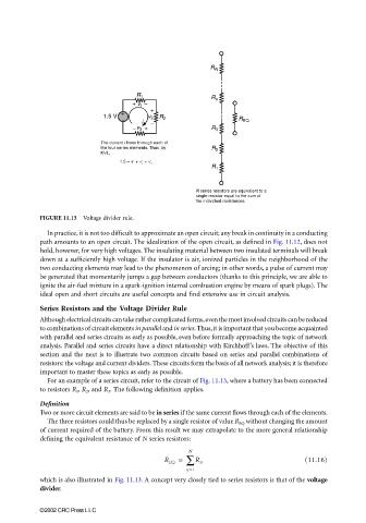
FIGURE 11.13 Voltage divider rule.
In practice, it is not too difficult to approximate an open circuit; any break in continuity in a conducting
path amounts to an open circuit. The idealization of the open circuit, as defined in Fig. 11.12, does not
hold, however, for very high voltages. The insulating material between two insulated terminals will break
down at a sufficiently high voltage. If the insulator is air, ionized particles in the neighborhood of the
two conducting elements may lead to the phenomenon of arcing; in other words, a pulse of current may
be generated that momentarily jumps a gap between conductors (thanks to this principle, we are able to
ignite the air-fuel mixture in a spark-ignition internal combustion engine by means of spark plugs). The
ideal open and short circuits are useful concepts and find extensive use in circuit analysis.
Series Resistors and the Voltage Divider Rule
Although electrical circuits can take rather complicated forms, even the most involved circuits can be reduced
to combinations of circuit elements in parallel and in series. Thus, it is important that you become acquainted
with parallel and series circuits as early as possible, even before formally approaching the topic of network
analysis. Parallel and series circuits have a direct relationship with Kirchhoff’s laws. The objective of this
section and the next is to illustrate two common circuits based on series and parallel combinations of
resistors: the voltage and current dividers. These circuits form the basis of all network analysis; it is therefore
important to master these topics as early as possible.
For an example of a series circuit, refer to the circuit of Fig. 11.13, where a battery has been connected
to resistors R 1 , R 2 , and R 3 . The following definition applies.
Definition
Two or more circuit elements are said to be in series if the same current flows through each of the elements.
The three resistors could thus be replaced by a single resistor of value R EQ without changing the amount
of current required of the battery. From this result we may extrapolate to the more general relationship
defining the equivalent resistance of N series resistors:
N
R EQ ∑ R n (11.16)
=
n=1
which is also illustrated in Fig. 11.13. A concept very closely tied to series resistors is that of the voltage
divider.
©2002 CRC Press LLC