
Page 201 - The Mechatronics Handbook
P. 201
0066_Frame_C11 Page 7 Wednesday, January 9, 2002 4:14 PM
1 1 1
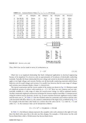
TABLE 11.1 Common Resistor Values ( / 8 -, / 4 -, / 2 -, 1-, 2-W Rating)
Ω Code Ω Multiplier kΩ Multiplier kΩ Multiplier kΩ Multiplier
10 Brn-blk-blk 100 Brown 1.0 Red 10 Orange 100 Yellow
12 Brn-red-blk 120 Brown 1.2 Red 12 Orange 120 Yellow
15 Brn-grn-blk 150 Brown 1.5 Red 15 Orange 150 Yellow
18 Brn-gry-blk 180 Brown 1.8 Red 18 Orange 180 Yellow
22 Red-red-blk 220 Brown 2.2 Red 22 Orange 220 Yellow
27 Red-vlt-blk 270 Brown 2.7 Red 27 Orange 270 Yellow
33 Org-org-blk 330 Brown 3.3 Red 33 Orange 330 Yellow
39 Org-wht-blk 390 Brown 3.9 Red 39 Orange 390 Yellow
47 Ylw-vlt-blk 470 Brown 4.7 Red 47 Orange 470 Yellow
56 Grn-blu-blk 560 Brown 5.6 Red 56 Orange 560 Yellow
68 Blu-gry-blk 680 Brown 6.8 Red 68 Orange 680 Yellow
82 Gry-red-blk 820 Brown 8.2 Red 82 Orange 820 Yellow
FIGURE 11.9 Resistor color code.
Thus, Ohm’s law can be rested in terms of conductance, as
I = GV (11.14)
Ohm’s law is an empirical relationship that finds widespread application in electrical engineering
because of its simplicity. It is, however, only an approximation of the physics of electrically conducting
materials. Typically, the linear relationship between voltage and current in electrical conductors does not
apply at very high voltages and currents. Further, not all electrically conducting materials exhibit linear
behavior even for small voltages and currents. It is usually true, however, that for some range of voltages
and currents, most elements display a linear i-v characteristic.
The typical construction and the circuit symbol of the resistor are shown in Fig. 11.8. Resistors made
–5
of cylindrical sections of carbon (with resistivity ρ = 3.5 × 10 Ω m) are very common and are com-
mercially available in a wide range of values for several power ratings (as will be explained shortly).
Another commonly employed construction technique for resistors employs metal film. A common power
rating for resistors used in electronic circuits (e.g., in most consumer electronic appliances such as radios
1
and television sets) is W. Table 11.1 lists the standard values for commonly used resistors and the color
--
4
code associated with these values (i.e., the common combinations of the digits b 1 b 2 b 3 as defined in Fig. 11.9.
For example, if the first three color bands on a resistor show the colors red (b 1 = 2), violet (b 2 = 7), and
yellow (b 3 = 4), the resistance value can be interpreted as follows:
R = 27 × 10 = 270,000 Ω = 270 kΩ
4
In Table 11.1, the leftmost column represents the complete color code; columns to the right of it only
show the third color, since this is the only one that changes. For example, a 10-Ω resistor has the code
brown-black-black, while a 100-Ω resistor has brown-black-brown.
©2002 CRC Press LLC