
Page 200 - The Mechatronics Handbook
P. 200
0066_Frame_C11 Page 6 Wednesday, January 9, 2002 4:14 PM
FIGURE 11.7 i-v characteristics of ideal sources.
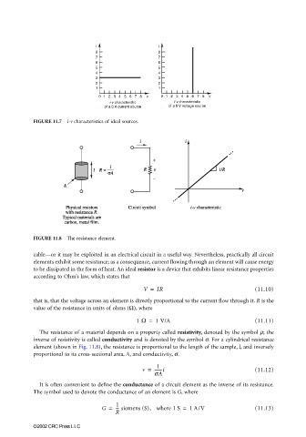
FIGURE 11.8 The resistance element.
cable—or it may be exploited in an electrical circuit in a useful way. Nevertheless, practically all circuit
elements exhibit some resistance; as a consequence, current flowing through an element will cause energy
to be dissipated in the form of heat. An ideal resistor is a device that exhibits linear resistance properties
according to Ohm’s law, which states that
V = IR (11.10)
that is, that the voltage across an element is directly proportional to the current flow through it. R is the
value of the resistance in units of ohms (Ω), where
1 Ω = 1 V/A (11.11)
The resistance of a material depends on a property called resistivity, denoted by the symbol ρ; the
inverse of resistivity is called conductivity and is denoted by the symbol σ. For a cylindrical resistance
element (shown in Fig. 11.8), the resistance is proportional to the length of the sample, l, and inversely
proportional to its cross-sectional area, A, and conductivity, σ.
1
v = -------i (11.12)
sA
It is often convenient to define the conductance of a circuit element as the inverse of its resistance.
The symbol used to denote the conductance of an element is G, where
1
G = --- siemens (S), where 1 S = 1 A/V (11.13)
R
©2002 CRC Press LLC