
Page 209 - The Mechatronics Handbook
P. 209
0066_Frame_C11 Page 15 Wednesday, January 9, 2002 4:14 PM
FIGURE 11.20 Models for practical ammeter and
voltmeter.
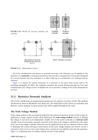
FIGURE 11.21 Measurement of power.
All of the considerations that pertain to practical ammeters and voltmeters can be applied to the
operation of a wattmeter, a measuring instrument that provides a measurement of the power dissipated
by a circuit element, since the wattmeter is in effect made up of a combination of a voltmeter and an
ammeter.
Figure 11.21 depicts the typical connection of a wattmeter in the same series circuit used in the
preceding paragraphs. In effect, the wattmeter measures the current flowing through the load and,
simultaneously, the voltage across it multiplies the two to provide a reading of the power dissipated by
the load.
11.3 Resistive Network Analysis
This section will illustrate the fundamental techniques for the analysis of resistive circuits. The methods
introduced are based on Kirchhoff’s and Ohm’s laws. The main thrust of the section is to introduce and
illustrate various methods of circuit analysis that will be applied throughout the book.
The Node Voltage Method
Node voltage analysis is the most general method for the analysis of electrical circuits. In this section, its
application to linear resistive circuits will be illustrated. The node voltage method is based on defining
the voltage at each node as an independent variable. One of the nodes is selected as a reference node
(usually—but not necessarily—ground), and each of the other node voltages is referenced to this node.
Once each node voltage is defined, Ohm’s law may be applied between any two adjacent nodes in order
to determine the current flowing in each branch. In the node voltage method, each branch current is
expressed in terms of one or more node voltages; thus, currents do not explicitly enter into the equations.
Figure 11.22 illustrates how one defines branch currents in this method.
©2002 CRC Press LLC